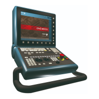
Hardware configuration
CNC 8065
(REF: 1404)
·3·
INDEX
About the product ......................................................................................................................... 5
Declaration of conformity .............................................................................................................. 9
Version history ............................................................................................................................ 11
Safety conditions ........................................................................................................................ 13
Warranty terms ........................................................................................................................... 17
Material returning terms.............................................................................................................. 19
CNC maintenance ...................................................................................................................... 21
CHAPTER 1 PREVIOUS INFORMATION.
CHAPTER 2 HARDWARE STRUCTURE.
2.1 Possible configurations. ................................................................................................. 27
CHAPTER 3 HEAT DISSIPATION. CENTRAL UNIT (CPU) ENCLOSURE.
3.1 Heat dissipation models................................................................................................. 32
CHAPTER 4 CENTRAL UNIT ICU.
4.1 Technical characteristics................................................................................................ 36
4.2 ICU central unit dimensions. .......................................................................................... 38
4.2.1 Dimensions of the central unit without monitor. ......................................................... 38
4.2.2 Central unit with LCD-15 / LCD-15 TOUCH monitor (rear mounting). ....................... 39
4.2.3 Central unit with LCD-10K monitor (option 1) (rear mounting)................................... 40
4.2.4 Central unit with LCD-10K monitor (option 2) (rear mounting)................................... 41
4.3 Dimensions and characteristics of the enclosure........................................................... 42
4.4 Elements (connectors). .................................................................................................. 44
4.4.1 Peripheral board......................................................................................................... 44
4.4.2 Expansion board. ....................................................................................................... 47
4.4.3 CPU board. ................................................................................................................ 50
4.4.4 Operator panel (only LCD-10K) ................................................................................. 52
4.4.5 Digital inputs and outputs. Electrical characteristics. ................................................. 53
4.4.6 Feedback inputs. Technical characteristics and connection. ..................................... 54
4.5 Power connection. ......................................................................................................... 56
4.6 Housing for the compact flash and battery-powered RAM memory. ............................. 57
4.7 RS232 serial line connection. ........................................................................................ 58
4.8 RS422 serial line connection. ........................................................................................ 60
4.9 RS485 serial line connection. ........................................................................................ 62
4.10 Probe connection. .......................................................................................................... 64
4.11 Connection to an Ethernet network................................................................................ 66
CHAPTER 5 LCD-15SVGA. PASSIVE MONITOR " LCD15-SVGA".
5.1 Possible configurations. ................................................................................................. 68
5.2 Technical characteristics................................................................................................ 69
5.3 Hardware dimensions. ................................................................................................... 70
5.4 Dimensions and characteristics of the enclosure........................................................... 71
5.5 Elements (connectors). .................................................................................................. 72
5.6 Overall connection. ........................................................................................................ 74
CHAPTER 6 HORIZONTAL-KEYB MODULE. HORIZONTAL KEYBOARD WITH OR WITHOUT MOUSE.
6.1 Hardware dimensions. .................................................................................................. 76
6.2 Dimensions and characteristics of the enclosure........................................................... 77
6.3 Elements (connectors). .................................................................................................. 78
CHAPTER 7 VERTICAL-KEYB MODULE. VERTICAL KEYBOARD WITH OR WITHOUT MOUSE.
7.1 Hardware dimensions. .................................................................................................. 82
7.2 Dimensions and characteristics of the enclosure........................................................... 83
7.3 Elements (connectors). .................................................................................................. 84

 Loading...