Drives
3.
180
Ref.1912
DDS
HARDWARE
· 156 ·
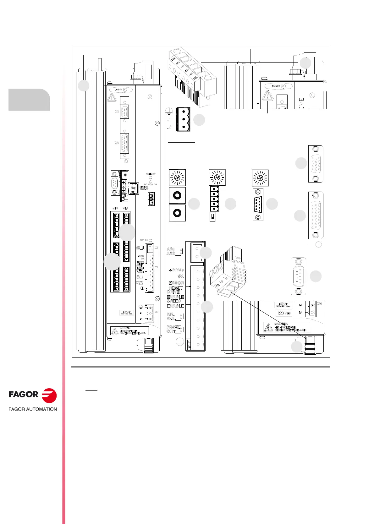
CMC 2.35/2.50
These drives have the following connectors:
F. H3/112
CMC 2.35|2.50 compact drives. Connectors.
1. Power connector for motor (U, V, W) and mains connection (R, S, T).
Note
. RST has been the classic nomenclature for mains phases. L1L2L3 is its equivalent nowadays.
2. Connector for the external Ballast resistor (Re) and for accessing the power bus (L+, L-).
3. External Ballast resistor.
X1. Connector for the internal 24 V DC power supply (2-ph, with line voltage V AC).
X2. Connector for the basic control signals.
X3. Connector with two possible uses:
• as output of the encoder simulator.
• as input of the direct feedback for the position loop.
X4. Connector for motor feedback connection (encoder).
X5. Connector for RS-232 serial line connection.
X6.
Possible connectors that may be located in this position:
• SERCOS-II
a
or CAN
b
interface connector (always with X5).
• Connector for RS-232/422
c
serial line connection (never with X5).
X7. Connector for external acknowledgment of the status of the safety relay.
SL1. Slot for the cards A1, 16DI-8DO and 8DI-16DO.
SL2. Slot for the cards 16DI-8DO and 8DI-16DO.
External Ballast resistor
top view
CANSERCOS RS422
(a) (b) (c)
NODE
SELECT
NODE
SELECT
0
1
0
4
8
4
0
8
0
4
8
1
2
3
4
5
1
9
NODE
SELECT
OUT
IN
3
X1
1
X6 X6 X6
2
SL1
SL2
Possibilities:
X5. Serial line RS-232 + (X6. SERCOS
a
or X6. CAN
b
)
or X6. Serial line RS-232/422
c
·without X5·
RESET button
WARNING. AC touch current greater than
3.5 mA. Install a ground wire with a section
of at least 10 mm² (Cu) or 16 mm² (Al).
X4
X5
X3
BOOT button.
Software update.
SERCOS|CAN transmission
speed selection.
X7
X2
bottom
view
or