Auxiliary modules
4.
AUXILIARY MODULES
Bus protection module. BPM
200
Ref.1912
DDS
HARDWARE
· 196 ·
4.6 Bus protection module. BPM
Install in DDS systems having:
Synchronous spindle and only when required by the application.
Purpose. Protect the power semi-conductors (IGBTs) of the drive that
governs it, thus preventing damage to the unit due to a very high voltage that
may be generated at the power bus because the braking energy cannot be
returned when a voltage drop occurs.
and/or,
RPS power supply when only the controlled stop is to be ensured.
Purpose. To ensure a controlled stop of the motor due to mains failure
because the energy may be dissipated while braking at the external Ballast
resistors installed in the BPM module. Not installing this module will result in
an uncontrolled stop (by friction) in case of a voltage failure due to an over-
voltage error of the bus because there are no resistors to dissipate the
braking energy.
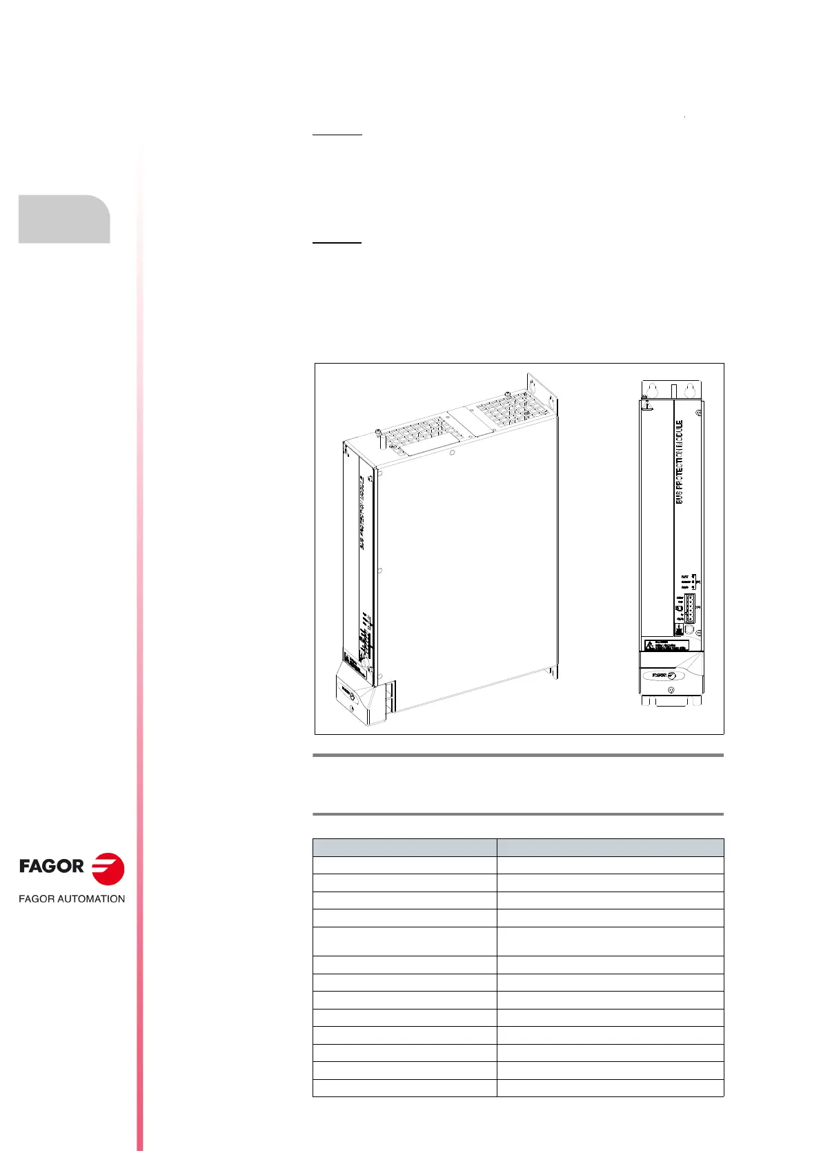
Outside look
Technical data
F. H4/11
Bus Protection Module, BPM. Outside look.
T. H4/13 Bus Protection Module, BPM. Technical data.
Bus Protection Module BPM
Power voltage input 542-800 V DC
Control circuit voltage 24 V DC (between 22-26 V DC)
Control circuit consumption 0.1 A
Protections Short-circuit, over-temperature
Ballast resistors
≥ 18 Ω. Up to three 18 Ω resistors
may be connected without power limit
Maximum braking power 100 kW
Filter capacity 410 µF, 900 V DC
Max. voltage at DR OK contact 125 V AC, 150 V DC
Max. current at DR OK contact 1 A
Approx. mass kg/lb 3.6/7.9
Ambient temperature 0°C/45°C (32°F/113°F)
Storage temperature -25°C/60°C (-13°F/140°F)
Maximum humidity
< 90 % (non condensing at 45°C/113°F)