Auxiliary modules
AUXILIARY MODULES
Bus protection module. BPM
4.
Ref.1912
· 197 ·
DDS
HARDWARE
Chapter 11. DIMENSIONS of this manual shows their dimensions.
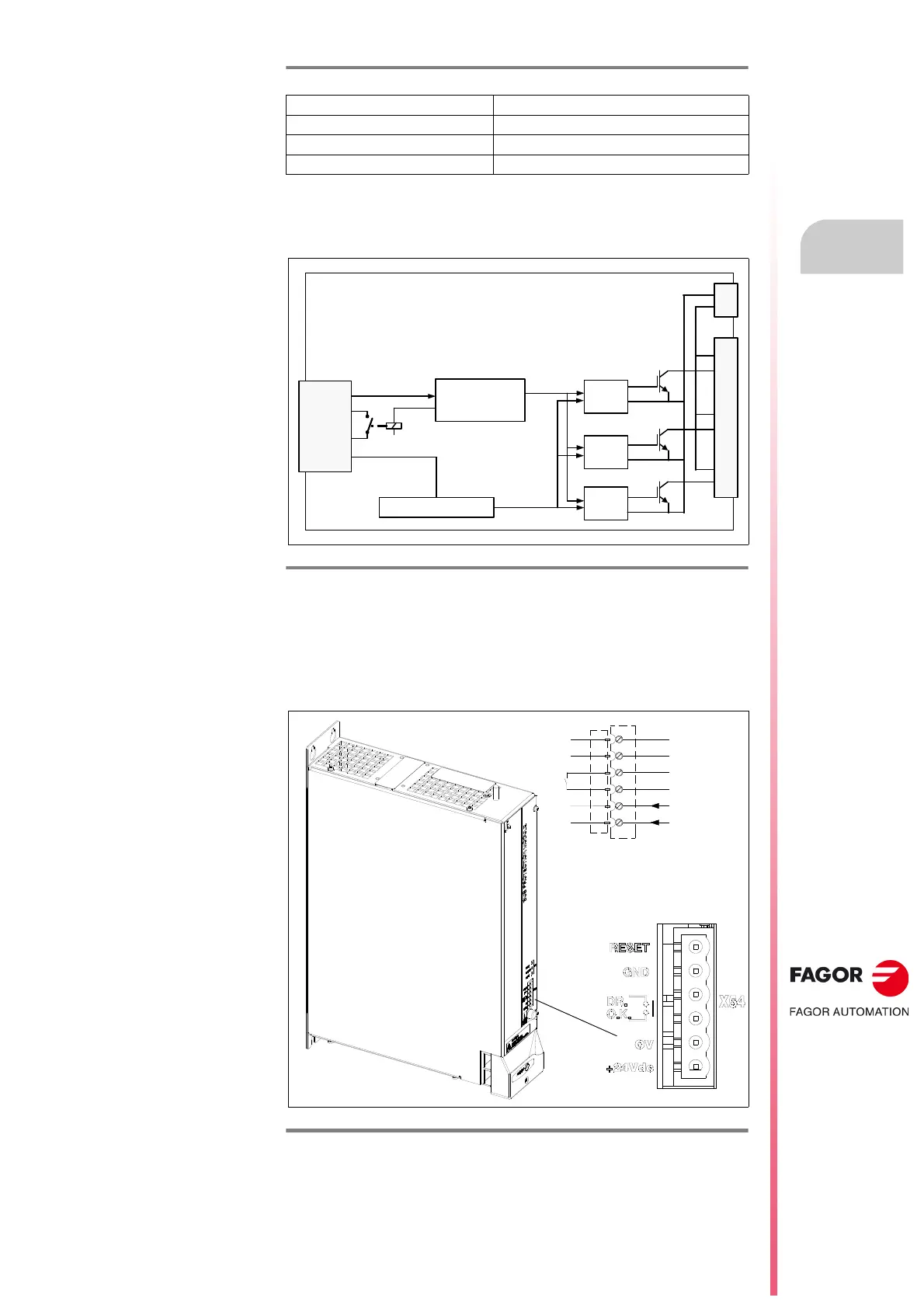
Block diagram
Connectors
X54 connector. Basic control signals
Screw-in connection type 6-pin plug-in connector located at the front of the
module and identified as X54. See figure.
Maximum altitude 2 000 m (6 561 ft) above sea level
Operating vibration 1 g
Shipping vibration 1.5 g
Sealing IP 2x
F. H4/12
Bus Protection Module, BPM. Block diagram.
F. H4/13
X54 connector. Basic control signals.
T. H4/13 Bus Protection Module, BPM. Technical data.
INTERMEDIATE
CIRCUIT CONTROL
24 V DC
BPM OK.
X54
0 V DC
POWER SUPPLY
DRIVER
IGBT
L -
X56
L +
R1
R1
R2
R2
R3
R3
DRIVER
IGBT
DRIVER
IGBT
RESET
GND
GND
DRIVE OK
0 V DC (IN)
24 V DC (IN)
1
2
3
4
5
6
RESET