Installation
8.
Ref.1912
· 307 ·
DDS
HARDWARE
Identifying the axes with addresses higher than 15 requires setting QP13.
See this parameter in chapter 13 of the “man_dds_soft.pdf” manual.
In order to establish communication via RS-232 serial line, the direction of
the arrow of the switch of the corresponding module must coincide with the
zero identifier.
Interconnection
Use the RS-232/422 cable to connect all the drives that will be governed by
the video terminal. See chapter
7. CABLES of this manual.
RS-232/422 serial line connection with and ESA VT
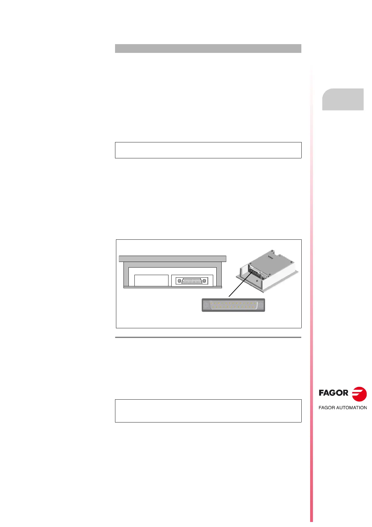
The RS-232/422 connection of the ESA terminal with the drives is made
through the MSP connector located at the bottom of the VT module.
See
figure.
The MSP serial port (
Multi Serial Port) is a part of any ESA Video Terminal
and is used to connect it with other devices. Hence, the project is transferred
from the PC to the VT through this port.
This port is accessed from a 25-pin female SUB-D connector and may
establish communication with other devices through RS-232, RS-422, RS-
485 and C.L. (TTY-20 mA) protocols.
Example
How to identify an axis addressed in position 26 in the system when
communicating via RS-422 serial line?
When the identifier of the axis is higher than 15 (like in this case), QP13
must be set so it meets the ratio:
Defined ID = ID to be selected at the rotary switch + (15 x QP13).
Hence, for
defined ID = 26, select C (same as 11) at the drive's rotary
“NODE SELECT” switch and set QP13=1.
NOTE. The module must be reset in order for any change made on the
rotary switch to be effective.
F. H8/47
MSP connector of the ESA video terminal for the RS-422 connection.
NOTE. Pin 16 does not contemplate communicating with any type of load.
Any disturbance going into this pin can damage the video terminal and
the process.
Sub-D, F25
- Front view -
[ Sub-D, F25 ]
1
13
14 25
ESA panel (VT 150W)
Bottom view