Connection diagrams
10.
Ref.1912
· 353 ·
DDS
HARDWARE
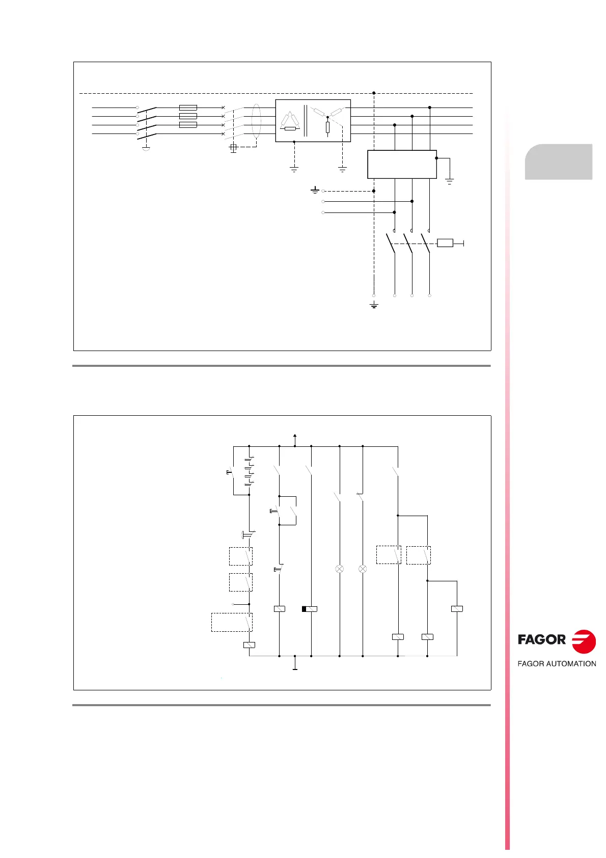
Diagram for general connection to mains
Diagram of the maneuver
F. H10/2 6
ACD/SCD compact drive, CAN. Diagram for general connection to mains.
F. H10/2 7
Compact DDS system. ACD/SCD, CAN. Diagram of the maneuver.
PE
- S1
MECHANICAL
MAIN SWITCH
- F3
- F4
- F5
MAIN FILTER 42A-A
L1
L1L2L3
3x 400-460 VAC
2x 400-460 VAC
L1
L2
L3
CONTACTOR
- KM1
L2
N
- Q1
DIFFERENTIAL
BREAKER
WARNING. When using an isolating transformer, the secondary must be
connected in star and its middle point must be connected to GND.
POWER MAINS
IT A MUST TO USE FUSES
TO THE X1
CONNECTOR
TO THE POWER CONNECTOR
ACD/SCD COMPACT DRIVES
L1
L2
L3
Note.
Observe that having the main key -S1 closed, although the power
contactor - KM1 is open, the internal 24 auxiliary power supply of the
unit remains connected through its connector X1 to feed the control
circuits of the drive.
Important.
The relay KA3 uses delayed
deactivation (t seconds)
maintaining the DRIVE ENABLE
control signal active for a few
seconds to maintain motor torque
while the vertical axis holding
brake is enabled.
See parameter GP9 in the
“man_dds_soft.pdf” manual.
Note.
CNC EMERG. will always be
assigned to I1/O1 of the PLC with
an 8055/55i CNC. With an 8070
CNC, it may be assigned to any I/O
of the PLC. The contacts
associated with relays - KA3, - KA4
and - KA6 are shown in fig.
F.
H10/25
and the contactor - KM1 in
fig.
F. H10/26
.
KA3
-KA6
EMERG.
STOP
DR.X
OK
DR.Z
OK
I1 PLC
CNC EMERG.
O1 PLC
-KA1
EMERGENCY LINE
GND
ON OFF
TO SPEED ENABLES
-KA4
BRAKE
CONTROL
BRK
(See GP9)
CNC
ENABLE
X
CNC
ENABLE
Z
KM1
KA3
KM1
+24VDC
X+
X-
Z+
Z-
KA1
ON
KM1
OFF
-KM1
DELAY OFF
-KA3
DRIVE
ENABLES
ON
Green
OFF
Red
t seconds