Power supplies
2.
94
Ref.1912
DDS
HARDWARE
· 90 ·
A 1.25 A fuse protects the internal circuits.
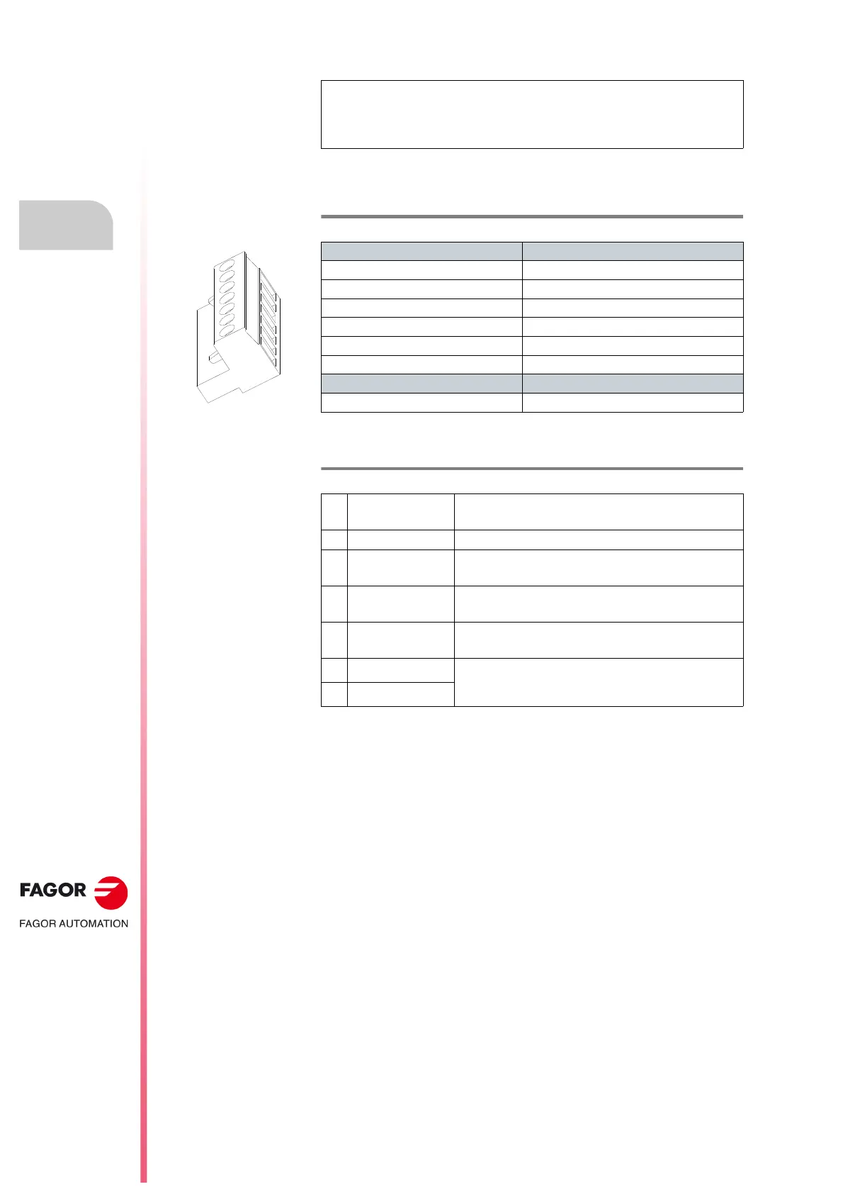
The following table shows the values for gap, tightening torque, sections of
the screws and other data of the plug-in connector for X6.
The next table shows the signals and other considerations related to each
pin of connector X6:
NOTE. Remember that the internal circuits of PS-65A non-regenerative
power supplies must be powered by an auxiliary 24 V DC power supply,
“APS-24”; that's why its control connector has three terminals more than
connector X6 of the RPS.
T. H2/35 Plug-in connector for X6. Technical data.
Connector data RPS-80 | RPS-75 | RPS-45 | RPS-20
Nr of poles 7
Gap (mm) 5.00
Min./max. tightening torque (N·m) 0.5/0.6
Screw thread M3
Min./max. section (mm²) 0.2/2.5
Rated current In (A) 12
Wire data
Length to strip (mm) 7
T. H2/36 Connector X6. Description of the pins.
1
ERROR RESET
System error RESET input
(24 V DC; 4.5-7 mA).
2
N.C. Not Connected
3
GND
0 volts reference for digital inputs.
Error RESET (1) and System Speed Enable (5).
4
PWM ENABLE
Safety.
Power bus voltage enable input (24 V DC).
5
SYSTEM SPEED
ENABLE
General system speed enable.
(24 V DC; 4.5-7 mA).
6
SYSTEM OK
Contact indicating module status.
It opens in case of failure.
Limit 1 A at 24 V.
7
SYSTEM OK