Power supplies
2.
Ref.1912
· 91 ·
DDS
HARDWARE
Module power-up
When turning on the RPS power supply module or doing a reset, various
messages appear on its seven-segment display:
Software version, after the r with the identifying digits.
Error listing.
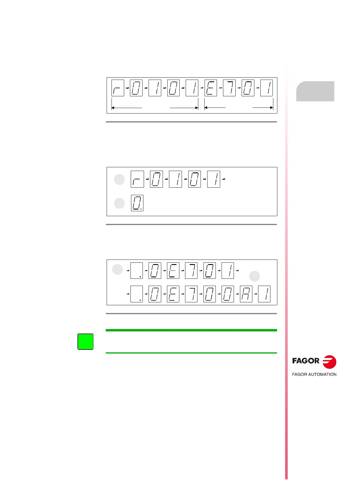
Stages shown on the 7-segment display:
Software version displaying stage. It shows the software version loaded
in the module. It first shows the letter r (indicating the version «release»),
followed by the version number (digit by digit) (A). When the drive is
active and the axis is being governed, the display will show the zero digit
with a blinking dot (B).
Final stage. It displays error messages (C) or warnings
(D) on the display
when they come up. When the series ends, it begins a new sequence
again repeating these messages again.
See the meaning of errors and warnings that may be shown on the display
in chapter
14. ERROR CODES AND MESSAGES of the “man_dds_ soft.pdf”
manual.
The system will not start running until all the errors detected at the power
supply have been eliminated.
Eliminating it requires first removing whatever caused it and if it cannot be
eliminated through the Error Reset input (pin 1 of X6), it will then require
doing an «error reset». This “RESET” may be activated from the RESET
button that the power supply has on top of the status display and the
switches for selecting the DC BUS voltage.
F. H2/48
Module startup stages.
F. H2/49
Stage to display the software version and other indications.
F. H2/50
Final stage. Error and warning displaying STAGE.
INFORMATION. RPS power supplies do not inform the user of any type of
warning or error message on the CNC screen. They only do it on their own
display.