CQR-30/56 Fagor Compact Drives and Motors Quick Reference. Ref.1910
DIMENSIONS
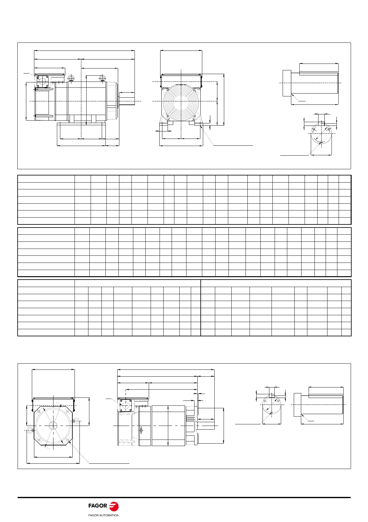
FM7. E01|E02 series. Foot mounting
FM7. E01|E02 series. Flange mounting
Units in mm
ABCDEFGHhJKDLMNPRXBYZSQ
FM7-A037-
3
-E0
324.0 113.0 100 174 80.0 70.0 9 250 - 34 34.0 499.0 188 168 110.5 175.0 45 31 12 174
FM7-A055-
3
-E0
286.0 117.0 112 204 95.0 50.0 10 269 247.0 75 42.5 486.0 220 129 114.0 200.0 70 55 12 204
FM7-A075-
3
-E0
296.0 137.0 112 204 95.0 70.0 10 269 247.0 75 42.5 546.0 220 177 114.0 250.0 70 55 12 204
FM7-A090-
3
-E0
317.0 156.0 112 204 95.0 89.0 10 269 247.0 75 42.5 586.0 220 215 114.0 269.0 70 55 12 204
FM7-A110-
3
-E0
264.0 196.0 160 279 127.0 89.0 16 343 331.5 55 42.5 571.0 290 223 131.0 307.0 108 84 15 260
FM7-A150-
3
-E0
264.0 196.0 160 279 127.0 89.0 16 343 331.5 55 42.5 571.0 290 223 131.0 307.0 108 84 15 260
Units in inches
ABCDEFGHhJKDL MNPRXBYZSQ
FM7-A037-
3
-E0
12.76 4.45 3.94 6.85 3.15 2.76 0.35 9.84 - 1.34 1.34 19.65 7.40 6.61 4.35 6.89 1.77 1.22 0.47 6.85
FM7-A055-
3
-E0
11.26 4.61 4.41 8.03 3.74 1.97 0.39 10.59 9.72 2.95 1.67 19.13 8.66 5.08 4.49 7.87 2.76 2.16 0.47 8.03
FM7-A075-
3
-E0
11.65 5.39 4.41 8.03 3.74 2.76 0.39 10.59 9.72 2.95 1.67 21.50 8.66 6.97 4.49 9.84 2.76 2.16 0.47 8.03
FM7-A090-
3
-E0
12.48 6.14 4.41 8.03 3.74 3.50 0.39 10.59 9.72 2.95 1.67 21.50 8.66 8.46 4.49 10.59 2.76 2.16 0.47 8.03
FM7-A110-
3
-E0
10.39 7.72 6.30 11.00 5.00 3.50 0.63 13.50 13.05 2.16 1.67 22.48 11.42 8.78 5.16 12.09 4.25 3.31 0.59 10.24
FM7-A150-
3
-E0
10.39 7.72 6.30 11.00 5.00 3.50 0.63 13.50 13.05 2.16 1.67 22.48 11.42 8.78 5.16 12.09 4.25 3.31 0.59 10.24
Units in mm Units in inches
QQKQR S T U W dmQ QK QR S T U W dm
FM7-A037-
3
-E0
60 45 1.0 28h6 7h11 4.0 8h9 22 M4 2.36 1.77 0.039 1.10h6 0.28h11 0.16 0.31h9 0.87 M4
FM7-A055-
3
-E0
80 70 2.0 32h6 8h11 5.0 10h9 22 M5 3.15 2.76 0.078 1.26h6 0.31h11 0.20 0.39h9 0.87 M5
FM7-A075-
3
-E0
110 90 0.5 48h6 9h11 5.5 14h9 40 M5 4.33 3.54 0.019 1.89h6 0.35h11 0.21 0.55h9 1.57 M5
FM7-A090-
3
-E0
110 90 0.5 48h6 9h11 5.5 14h9 40 M5 4.33 3.54 0.019 1.89h6 0.35h11 0.21 0.55h9 1.57 M5
FM7-A110-
3
-E0
110 90 1.0 48h6 9h11 5.5 14h9 40 M5 4.33 3.54 0.039 1.89h6 0.35h11 0.21 0.55h9 1.57 M5
FM7-A150-
3
-E0
110 90 1.0 48h6 9h11 5.5 14h9 40 M5 4.33 3.54 0.039 1.89h6 0.35h11 0.21 0.55h9 1.57 M5
L
AR
LF B
Q
F F XB
N
Y
SQ
KD
h
4 - Ø Z
Diameter of
mounting hole
M
E E
J
D
H
PC
G
Symbol indicating the direction of the cooling air
Note.
Only
shafts having a key
have tapped holes (M3,
10 mm deep) for mounting the coupling. See figure.
Detail of the shaft extension
4 - Ø Z
Diameter of
mounting hole
I
LC
KE
KI
KL
L
H
L
A
L
LL LR
LELF
LD
KD
D
Q
5
LG
LB
Detail of the shaft extension
Symbol indicating the direction of the cooling air