Fagor Compact Drives and Motors Quick Reference. Ref.1910 CQR-51/56
GROUND CONNECTION.
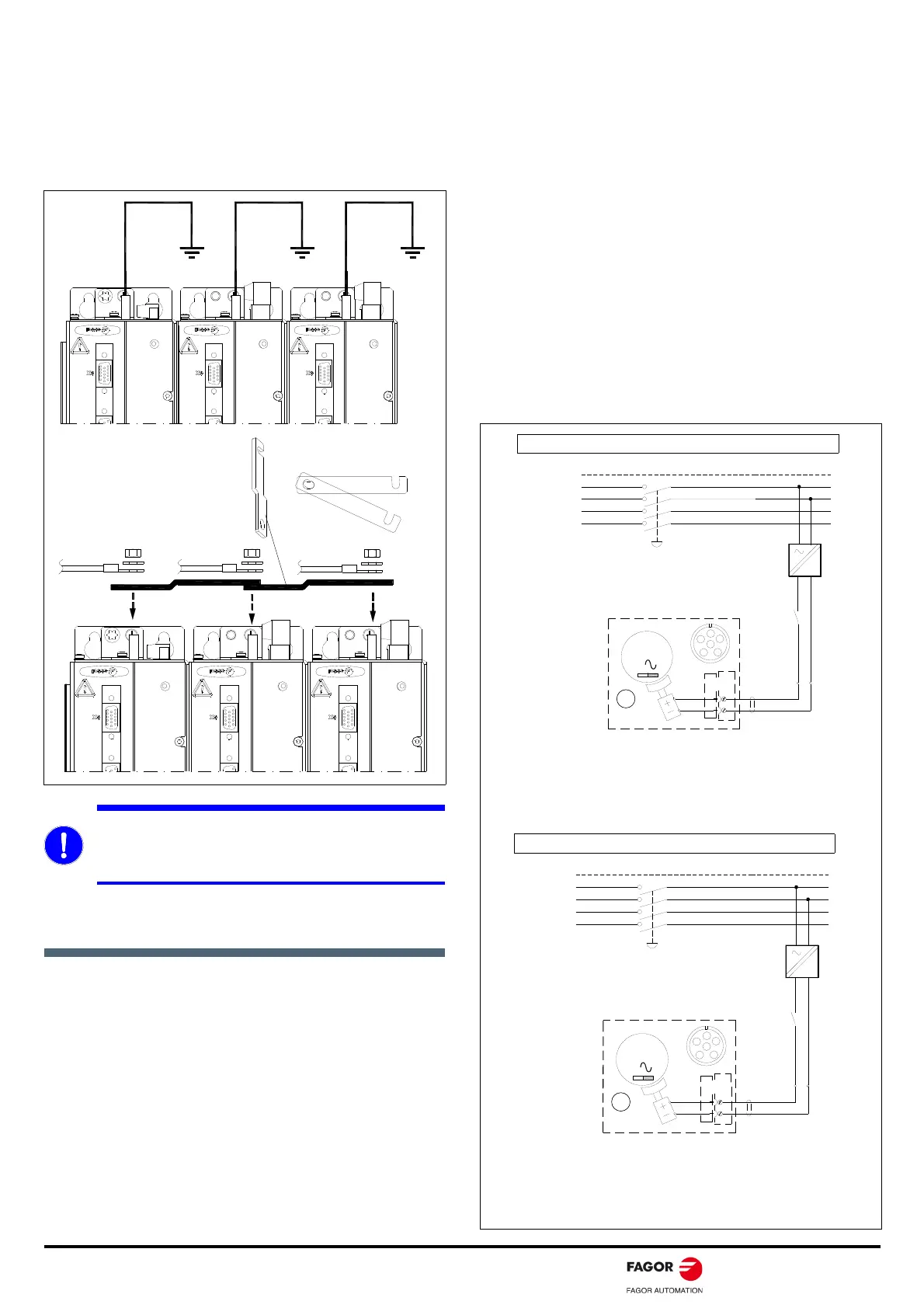
JOINING THE CHASSIS BETWEEN MODULES
The chassis of each module must be connected to the machine
ground point. Use the washers and nuts supplied with each module to
make the ground connection. The tightening torque must be between
2.3 and 2.8 N·m. Connecting these terminals by means of metal
plates offers mechanical ridigity; but it does ot guarantee proper
ground connection of each module.
ELECTRICAL DRAWING
The schematics of the following pages are only an orientation to
design the machine and may be expanded or reduced at wil.
Power-up procedure
Supply the compact drives by X1 (L1, L2) (400/460 V AC or
200/240 V AC) from mains. This will supply 24 V DC to the
internal control circuits, and outputs this 24 V DC by X2 (pin 1,
pin 2). Each module runs an internal test. If the test is successful,
the DR. OK contacts close.
Push ON button. This supplies power from mains to the compact
drive modules and activates the DRIVE ENABLE, X2 (pin 4) of
each drive.
Activate the control input SPEED ENABLE, X2 (pin 5) of each
drive from the CNC. The motor can now follow the velocity
command.
Emergency line
The - KA1 relay confirms that the system is mechanically and
electrically in working condition.
Error reset
This circuit configuration joins the error reset and the system power-
up in a single push-button.
Control from CNC
The CNC enables each axis and confirms the SPEED_ENABLE
signal to each drive by means of KA4 and KA6.
Stop
When the emergency line breaks or the OFF or - S1 keys are
opened, the control circuit of the drives must keep on working to
brake the motors, and the DRIVE ENABLE signal must be kept
active (24 V DC). The 24 V DC compact drive output voltage keep
the power to the control circuits, and the DRIVE ENABLE signals are
kept active while braking, by delaying the deactivation of - KA3.
HOLDING BRAKE SUPPLY CIRCUIT
The holding brake of the FKM motors is unlocked by applying +24 V
DC through a connector.
MANDATORY. Take a ground cable (as short as possible)
from each module to each main machine ground point. The
cable section must be the same as that of the cables
connected to the largest servomotor (at least 6 mm²).
PACT DRIVE
PACT DRIVE
PACT DRIVE
PACT DRIVE
PACT DRIVE
PACT DRIVE
FKM MOTOR
BRAKE
4
5
+24 VDC
0 VDC
BR
3
M
Z
4
5
+24 V
=
400 VAC
0 V
IMPORTANT.
Power
the holding brake
with a power supply
that provides
a continuous, stabilized voltage of 24 V DC.
To ensure safe operation in the event of large
temperature variations, the coil must be powered with
stabilized direct current.
PE
3x 400-460 VAC
L1
POWER MAINS
(R)
(S)
(T)
L2
L3
N
- S1
MECHANICAL MAIN SWITCH
FKM MOTOR
BRAKE
4
5
+24 VDC
0 VDC
BR
3
M
Z
4
5
+24 V
=
200 VAC
0 V
IMPORTANT.
Power
the holding brake
with a power supply
that provides
a continuous, stabilized voltage of 24 V DC.
To ensure safe operation in the event of large
temperature variations, the coil must be powered with
stabilized direct current.
PE
3x 200-240 VAC
L1
POWER MAINS
(R)
(S)
(T)
L2
L3
N
- S1
MECHANICAL MAIN SWITCH
Line voltage: 400 (1-10 %) V AC / 460 (1+10 %) V AC
Line voltage: 200 (1-10 %) V AC / 240 (1+10 %) V AC