CQR-50/56 Fagor Compact Drives and Motors Quick Reference. Ref.1910
This type of mains admits loads between one or several phases and
the neuter.
There are three kinds of TN diagrams depending on the relative
position of the neuter wire (N) and the protection wire (PE):
TN-S diagram where the neuter wire (N) and the protection wire
(PE) are different in the entire diagram.
TN-C-S diagram where the neuter and protection functions are
combined in a single wire (PEN) in part of the diagram.
TN-C diagram where the neuter and protection functions are
combined in a single wire (PEN) in the entire diagram.
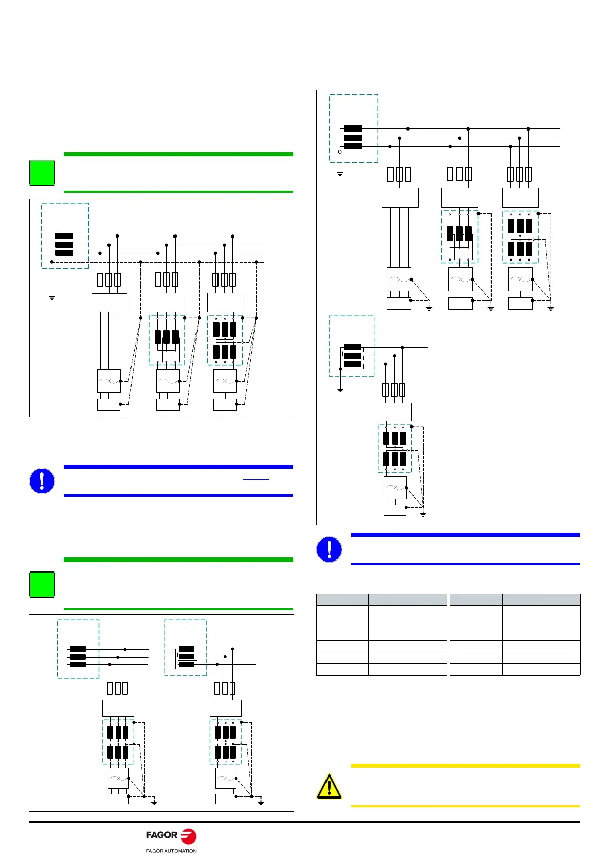
IT diagram
Distribution diagram that has no direct connection to ground and the
conductive parts of the installation are connected to ground.
With IT type distribution diagrams, the differential breaker is used
assuming that the capacitance of mains with respect to ground is
large enough to ensure that a minimum fault current flows with the
same magnitude as that of the operating differential current assigned.
Otherwise, its use is not necessary.
TT diagram
Distribution diagram that has a point directly connected to ground
and the conductive parts of the installation are connected to a ground
point independently from the ground electrode of the power supply
system.
CABLE SECTIONS
The table gathers the regulation applicable to typical installations of
drive systems. In any case, the cables must have a greater section or
the same as the ones connected to any motor. Determines the
maximum current in continuous duty cycle, admitted by 3-phase
conductors in PVC hoses and installed on the machines through
conduits and channels. The ambient temperature considered is
40°C/104°F.
INFORMATION. The DDS system may be connected
directly, through a transformer or auto-transformer in mains
with a TN type distribution diagram.
MANDATORY. With an IT distribution diagram, always
install
the DDS system to mains through an isolating transformer.
INFORMATION. Note that with an IT type distribution
diagram, mains can also be controlled through an isolation
watching device. Both protection measurements are
compatible with each other.
DDSDDS
L1
L2
L3
DIFFERENT IAL
BREAKER
DDS
SECONDARY
WINDING OF T H E
LINE T RANSFORMER
OF TH E PLANT
DIFFERENT IAL
BREAKER
DIFFERENT IAL
BREAKER
MAINS
FILTER
PEN
MAINS
FILT ER
MAINS
FILT ER
DDS
L1
L2
L3
SECONDARY
WINDING OF T H E
LINE T RANSFORMER
OF TH E PLANT
DIFFERENTIAL
BREAKER
MAINS
FILTER
L1
L2
L3
DDS
DIFFERENT IAL
BREAKER
SECONDARY
WINDING OF T H E
LINE TRANSFORMER
OF TH E PLANT
MAINS
FILTER
MANDATORY. “CORNER GROUNDED” type TT mains
require installing an isolating transformer.
SECTION MAX. CURRENT SECTION MAX. CURRENT
mm² A mm² A
0.75 8.5 6 30
110.11040
1.5 13.1 16 54
2.5 17.4 25 70
423.03586
WARNING. Before handling the power leads: Always
disconnect the 3-phase voltage at the electrical cabinet.
Wait, before handling these leads (about 4 min.).
The DDS system is designed to
support phase-chassis voltages
under 300 V AC.
It must be ensured that there is no
voltages over the indicated value if
an isolating transformer is not
installed; i.e. if the DDS system is
connected directly to mains or
through an auto-transformer.
Otherwise, protection elements
must be installed to avoid reaching
excessive voltages.
DDSDDS
L1
L2
L3
DIFFERENT IAL
BREAKER
DDS
SECONDARY
WINDING OF TH E
LINE TRANSFORMER
OF TH E PLANT
DIFFERENT IAL
BREAKER
D I F F ER EN T I A L
BREAKER
MAINS
FILTER
MAINS
FILT ER
MAINS
FILT ER
L1
L2
L3
DDS
DIFFERENT IAL
BREAKER
SECONDARY
WINDING OF T H E
LINE T RANSFORMER
OF TH E PLANT
MAINS
FILTER