CQR-48/56 Fagor Compact Drives and Motors Quick Reference. Ref.1910
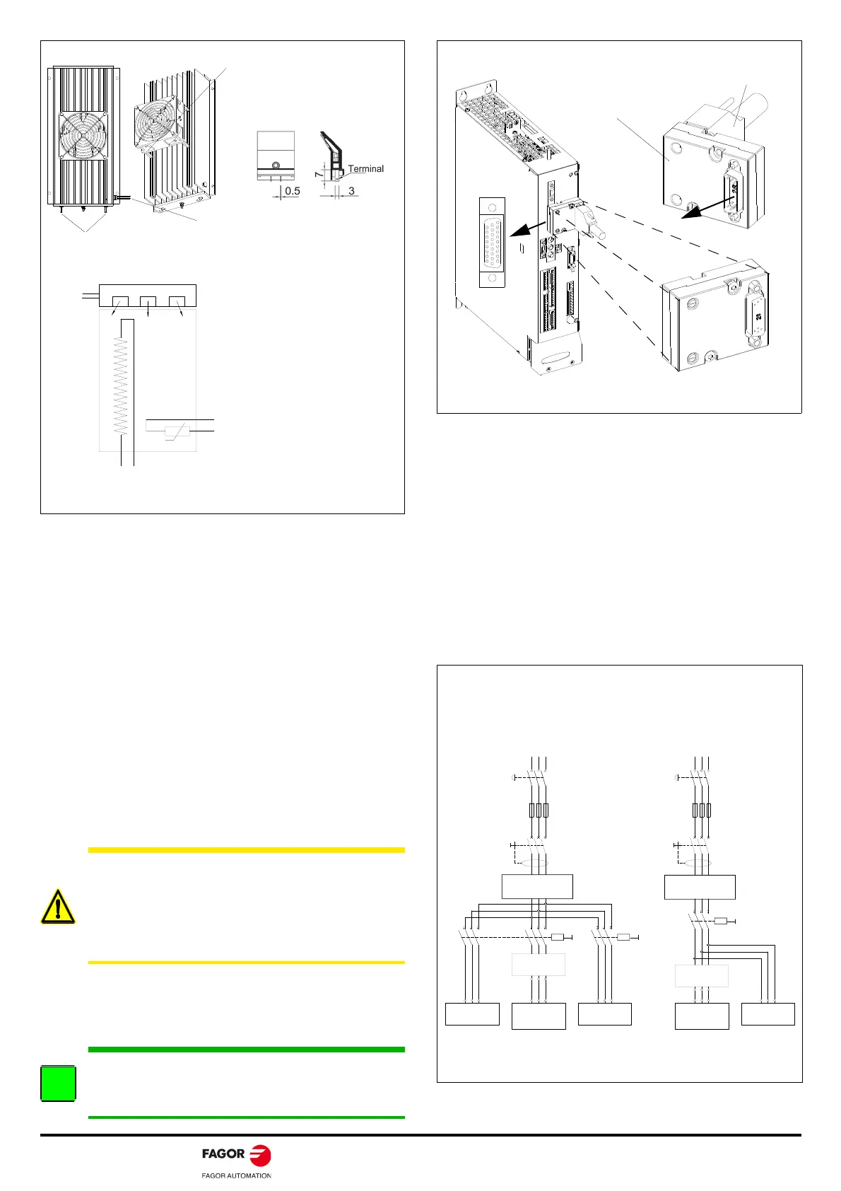
MOTOR DRIVE CONNECTIONS
Power connections
Connect the power cable MPC. Connect terminal U of the drive with
the terminal corresponding ti the U phase of the motor. Same as
terminals V-V, W-W, and PE-PE terminal of the drive and NOT to that
of the motor.
Feedback connections
Motor feedback connection
Connect the encoder cable (EEC-SP, EEC-FM7, EEC-FM7S, EEC-
FM7CS), accordingly to take the feedback from the motor to the
drive.
It is connected directly through the feedback cable between the
feedback connector of the motor and connector X4 of the drive
module as long as the isolation level required by FAGOR is
guaranteed between the motor temperature sensor and the power
circuit of the drive.
Note that installing the temperature sensor isolation adapter TSIA-1
means getting galvanic isolation between the temperature sensor of
the motor and the drive itself.
Direct feedback connection or encoder simulator connection
Connect the SEC-HD cable to take the encoder simulation from the
drive to the CNC, or connect the cable to take the feedback from
the sensor to the drive.
CABLING OF THE SYSTEM TO MAINS
Mains connection
The FAGOR DDS compact drive system is designed to be connected
to TN type 3-phase mains with values within the line voltage range
between 400 (1-10 %) V AC and 460 (1+10 %) V AC or 200 (1-10 %)
V AC and 240 (1+10 %) V AC and a line frequency of between 50 (1-
4 %) Hz and 60 (1+3.3 %) Hz.
Certain mandatory protection devices must be added to the mains
lines. Others are optional.
Connecting it to a different voltage range requires the use of
transformers or auto-transformers.
WARNING. FAGOR uses isolation systems between the
temperature sensors and the winding of their motors
ensuring long life to the motor-drive system regardless of
wiring lengths. When installing non-FAGOR motors, since it
cannot be guaranteed that the existing isolation will comply
with FAGOR standards, we recommend installing the
isolation adapter TSIA-1.
INFORMATION. Note that the isolation adapter TSIA-1 does
not check the encoder signals or the temperature sensor of
the motor. It only provides galvanic isolation of the
temperature sensor.
INTERNAL
THERMOSTAT
Tk
Tk
+ 24 V DC
PLC INPUT
160°C
L+
Re
AXIAL FAN
50/60 Hz
220/240 V AC
Always install it vertically
Ballast resistor
connection terminals
Tk connection terminals of the
internal thermostat
DIAGRAM.
Take either one of the two pins to + 24 V DC of the
external power supply of the electrical cabinet
and the other one to a PLC input.
IMPORTANT. Remember to manage the chosen PLC
input in the PLC program to generate an error
when exceeding the limit temperature (160°C)
detected by the sensor and to open the contact.
Take the Ballast resistor terminals to the Re and L+ terminals of the terminal
strip of the Ballast of the power supply.
FASTON type terminals for
connecting the fan
DIMENSIONS of the fan’s
FASTON terminals
Take the fan connection terminals to an outlet of the electrical
cabinet, single phase 50/60 Hz, 220/240 V AC.
Consumption: 0.15/0.13 A, 23/20 W.
Re
L+
TEMPERATURE SENSOR ISOLATION ADAPTER: TSIA-1
TSIA-1
Front view
ACD/SCD
TSIA-1.
Temperature sensor
isolation adapter
Motor feedback cable
Plug in and tighten the
two screws to connector
X4 of the drive
Note. The pinout of the temperature sensor isolation adapter TSIA-1 is
the same as that of connector X4 of the drive's motor feedback.
TSIA-1
Rear view
- S1
MECHANICAL
MAIN SWITCH
MAIN FILTER
42A-A
L3
L2
L1
(R)
CONTACTOR
- KM1
DIFFERENTIAL
BREAKER
POWER MAINS
IT A MUST TO
USE FUSES
TRANSFORMER oR
AUTOTRANSFORMER
3x 400-460 V AC
ACD/SCD/CMC
OTHER UNITS
- KM2
- Q1
CONTACTOR
OTHER UNITS
CONTACTOR
- KM1
TRANSFORMER oR
AUTOTRANSFORMER
DIFFERENTIAL
BREAKER
- Q1
IT A MUST TO
USE FUSES
- S1
MECHANICAL
MAIN SWITCH
- F
OTHER UNITS
L1 L2
L3
(S) (T) (R)
POWER MAINS
L1 L2
L3
(S) (T)
- F
3x 200-240 V AC
MAIN FILTER
42A-A
oR
L3
L2
L1
3x 400-460 V AC
ACD/SCD/CMC
3x 200-240 V AC
OR
Note. The mains filter may be installed indistinctly before or after the
power switch - KM1.
MAINS CONNECTION · TN TYPE
PROPER INSTALLATION
WRONG INSTALLATION
Note. RST, Classic nomenclature; L1L2L3, current nomenclature