CQR-52/56 Fagor Compact Drives and Motors Quick Reference. Ref.1910
If you decide not install the mains filter and electrical choke (on each
of the three power lines) or a transformer or an auto-transformer may
be installed instead. However, it does not ensure compliance with the
EC Directive.
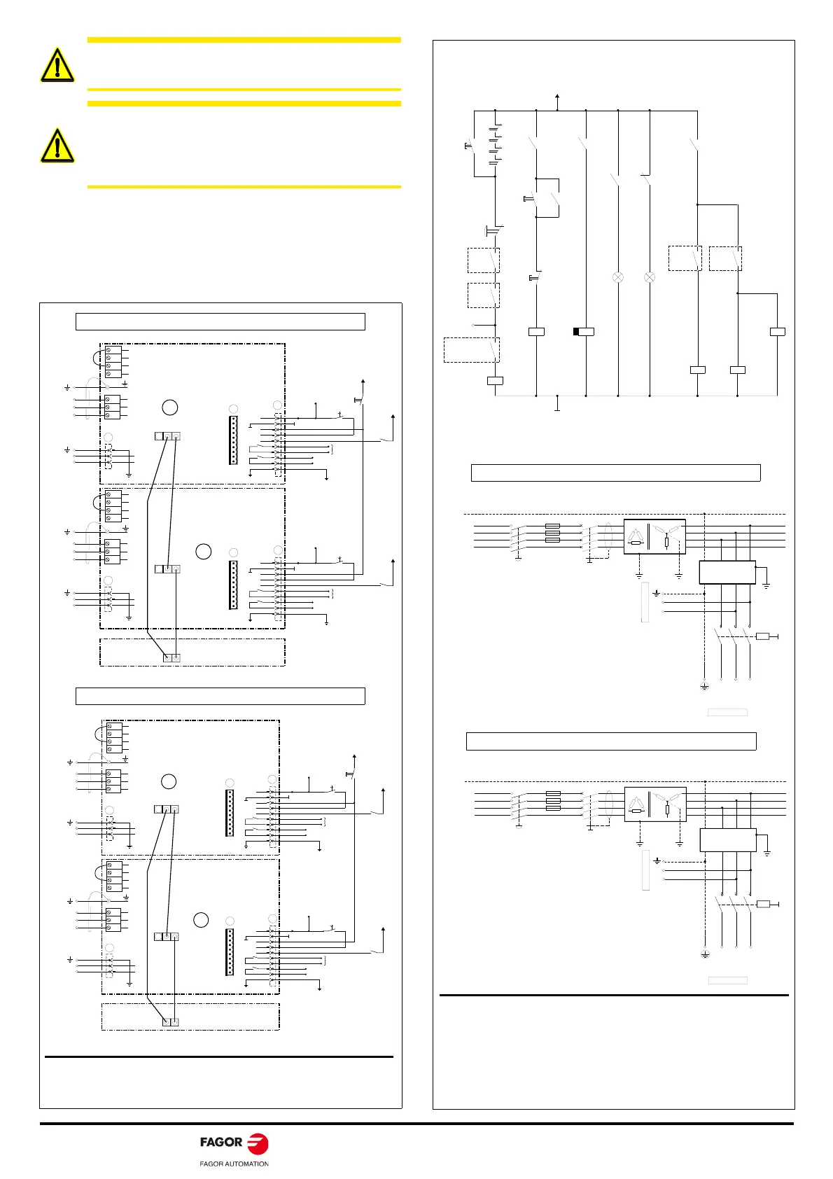
COMPACT SYSTEM WITH SERCOS CONNECTION
WARNING. When installing the motor, verify that the brake
releases the shaft completely before turning it for the first
time.
WARNING. Power the holding brake of the FKM motors
with a power supply that provides a continuous, stabilized
voltage of 24 V DC. To ensure safe operation in the event of
large temperature variations, the coil must be powered with
stabilized direct current.
X 1
X 1
+ 2 4 V D C
O U T
2
X
C O M P A C T
D R I V E
M O D U L E
S C D 1 . 1 5
C O M P A C T
D R I V E
M O D U L E
S C D 1 . 1 5
F A G O R C N C
R i
R e
L +
L -
R
L 1
L 2
L 3
3 x 4 0 0 / 4 6 0 V A C
I N
1
O U T
I N
I N
O U T
X 2
X 2
1
2
3
4
5
6
7
8
9
1 0
C H A S S I S
D R . X
O K
K A 4
S P E E D E N A B L E
D R I V E E N A B L E
E R R O R R E S E T
G N D
+ 2 4 V D C
O N
+ 2 4 V D C
K A 3
( P h o e n i x ,
5 . 0 8 m m )
1
1 0
Z
L 1
L 2
1
2
3
2 x 4 0 0 / 4 6 0 V A C
L 1
L 2
R i
R e
L +
L -
L 1
L 2
L 3
3 x 4 0 0 / 4 6 0 V A C
R
S
T
2 x 4 0 0 / 4 6 0 V A C
L 1
L 2
L 1
L 2
1
2
3
( P h o e n i x ,
5 . 0 8 m m )
1
1 0
X 2
X 2
1
2
3
4
5
6
7
8
9
1 0
C H A S S I S
D R . Z
O K
K A 6
+ 2 4 V D C
+ 2 4 V D C
K A 3
G N D
E R R O R R E S E T
D R I V E E N A B L E
S P E E D E N A B L E
S
T
X 1
X 1
+ 2 4 V D C
O U T
2
X
C O M P A C T
D R I V E
M O D U L E
S C D 1 . 1 5
C O M P A C T
D R I V E
M O D U L E
S C D 1 . 1 5
F A G O R C N C
R i
R e
L +
L -
R
L 1
L 2
L 3
3 x 2 0 0 / 2 4 0 V A C
I N
1
O U T
I N
I N
O U T
X 2
X 2
1
2
3
4
5
6
7
8
9
1 0
C H A S S I S
D R . X
O K
K A 4
S P E E D E N A B L E
D R I V E E N A B L E
E R R O R R E S E T
G N D
+ 2 4 V D C
O N
+ 2 4 V D C
K A 3
( P h o e n i x ,
5 . 0 8 m m )
1
1 0
Z
L 1
L 2
1
2
3
2 x 2 0 0 / 2 4 0 V A C
L 1
L 2
R i
R e
L +
L -
L 1
L 2
L 3
3 x 2 0 0 / 2 4 0 V A C
R
S
T
2 x 2 0 0 / 2 4 0 V A C
L 1
L 2
L 1
L 2
1
2
3
( P h o e n i x ,
5 . 0 8 m m )
1
1 0
X 2
X 2
1
2
3
4
5
6
7
8
9
1 0
C H A S S I S
D R . Z
O K
K A 6
+ 2 4 V D C
+ 2 4 V D C
K A 3
G N D
E R R O R R E S E T
D R I V E E N A B L E
S P E E D E N A B L E
S
T
Note. Compact modules do not have a “System Speed Enable” signal. In this
schematics, even when having SERCOS interface, electrical signals are used to
activate the enables.
Line voltage: 400 (1-10 %) V AC / 460 (1+10 %) V AC
Line voltage: 200 (1-10 %) V AC / 240 (1+10 %) V AC
EMERG.
STOP
DR.X
OK
DR.Z
OK
I1 PLC
CNC EMERG.
O1 PLC
-KA1
EMERGENCY LINE
GND
ON OFF
TO SPEED ENABLES
-KA4
-KA6
BRAKE
CONTROL
-BRK
CNC
ENABLE
X
CNC
ENABLE
Z
KM1
KA3
KM1
+24 V DC
X+
X-
Z+
Z-
KA1
ON
KM1
OFF
-KM1
DELAY OFF
-KA3
DRIVE
ENABLES
ON
Green
OFF
Red
t (s)
KA3
PE
- S1
MECHANICAL
MAIN SWITCH
- F1
- F2
- F3
MAIN FILTER 42A-A
L1
L1L2
L3
3x 400-460 VAC
2x 400-460 VAC
L1
CONTACTOR
- KM1
L2
- Q1
DIFFERENTIAL
BREAKER
WARNING.
When using an isolating transformer, the secondary must be
connected in star and its middle point must be connected to GND.
POWER MAINS
IT A MUST TO USE FUSES
TO THE X1
CONNECTOR
ACD/SCD COMPACT
DRIVES
TO THE POWER CONNECTOR
ACD/SCD COMPACT DRIVES
L2
L3
N
RST
3x 400-460 VAC
48 ... 62 Hz
PE
- S1
MECHANICAL
MAIN SWITCH
- F1
- F2
- F3
MAIN FILTER 42A-A
L1
L1L2
L3
3x 200-240 VAC
2x 200-240 VAC
L1
CONTACTOR
- KM1
L2
- Q1
DIFFERENTIAL
BREAKER
WARNING.
When using an isolating transformer, the secondary must be
connected in star and its middle point must be connected to GND.
POWER MAINS
IT A MUST TO USE FUSES
TO THE X1
CONNECTOR
ACD/SCD COMPACT
DRIVES
TO THE POWER CONNECTOR
ACD/SCD COMPACT DRIVES
L2
L3
N
R
S
T
3x 200-240 VAC
48 ... 62 Hz
Note. The relay - KA3 uses delayed deactivation t (s) maintaining the DRIVE
ENABLE control signal active for a few seconds to maintain motor torque while
the vertical axis holding brake is enabled.
CNC EMERG. will always be assigned to I1/O1 of the PLC with an 8055/55i
CNC. With an 8070 CNC, it may be assigned to any I/O of the PLC.
The 24 V DC for the DRIVE ENABLE signal should be taken from its own 24 V
DC power supply (X2, pin 1) to meet the EC Directives. (controlled stop on
mains failure).
Note. Observe that having the main key -S1 closed, although the power
contactor - KM1 is open, the internal 24 auxiliary power supply of the unit
remains connected through its connector X1 to feed the control circuits of
the drive.
Line voltage: 400 (1-10 %) V AC / 460 (1+10 %) V AC
Line voltage: 200 (1-10 %) V AC / 240 (1+10 %) V AC