CQR-34/56 Fagor Compact Drives and Motors Quick Reference. Ref.1910
Electrical characteristics
PRECAUTIONS WHEN INSTALLING THE MOTOR
This section describes the environmental precautions to bear in mind
when installing the motor
.
The motor must be installed under the following conditions:
Leave enough clearance for the cooling fan to blow the air out.
The minimum clearance between the machine and the exit of the
motor fan is 100 mm (3.94 in).
Install the motor in a clean place, away from oil and water. If there
is a chance that the motor may be exposed to oil or water, cover
it for protection. If dirty oil or water gets into the motor, it would
decrease the isolation resistance and cause a grounding failure.
Make sure that the motor is firmly secured to the floor or with the
flange because the weight of the motor the dynamic load when it
is running may generate vibrations.
Install the motor in an environment free of dust and metal
particles. The motor has an integrated fan with an internal
structure that provides cooling air to the motor. Blocking the air
flow with dust other strange elements may decrease the efficiency
of the cooling system.
CONSIDERATIONS FOR MOTOR INSTALLATION
Bear in mind the following considerations when installing the motor:
If it is a flange-mounted motor, it may be installed with its shaft at
the load end and at an angle between the horizontal and vertical
with the shaft facing down.
If it is a foot-mounted motor, it must be mounted with its feet
secured to the floor. If the motor is installed vertically, its shaft
must be facing down.
CAUTION !
Note that when installing transmission pulleys or
gearboxes, any blow to the shaft reduces its useful life, of
bearings, and may damage the encoder.
Therefore, do not hit it for any reason.
RADIAL LOADS
A misalignment between the motor shaft and the machine axis
increases vibration of the shaft and shortens the life of the ball
bearings and couplings. Likewise, exceeding certain maximum radial
load values may cause a similar effect of the ball bearings.
FM7. E01|E02 series
FM7. E03 series
FM7. HS3 series
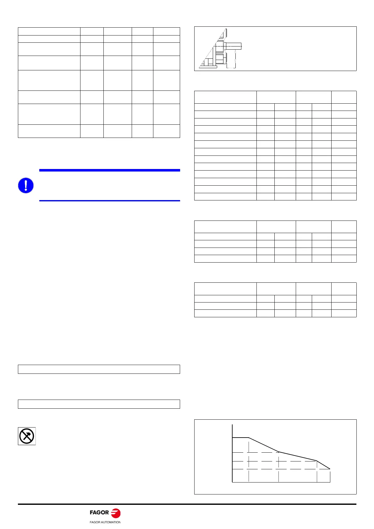
GRAPHS-RPM
When using mechanical transmission elements, the end of the motor
shaft may be subjet to radial loads.
Make sure that the maximum radial load values at the end of the
shaft do not exceed the permitted values shown on the graphs
depending on the rev/min of the shaft.
Exceeding these radial load values increases the vibration of the
shaft and shortens the life of the ball bearings and couplings.
The particular graph may be used to determine the permitted radial
loads that may be applied on to the end of the motor shaft depending
o its rev/min.
Motor Voltage Frequency Power Current
Units V AC Hz W A
FM7-A037--E0
400
460
50/60
60
37/51
60
0.11/0.14
0.16
FM7-A055--E0
FM7-D055-S1D0-E03
400
460
50/60
60
64/85
96
0.11/0.16
0.17
FM7-A075--E0
FM7-D075-S1D0-E03
FM7-D075-S1D0-HS3
400
460
50/60
60
41/62
63
0.07/0.10
0.09
FM7-A090--E0
400
460
50/60
60
45/58
63
0.11/0.10
0.10
FM7-A110--E0
FM7-D110-S1D0-E03
FM7-D110-S1D0-HS3
400
460
50/60
60
59/83
88
0.11/0.14
0.13
FM7-A150--E0
400
460
50/60
60
59/83
88
0.11/0.14
0.13
MANDATORY. The flange and the shaft of the motor have
an anticorrosive layer of paint or grease. The flange, the
shaft and the key must be cleaned before installing the
motor.
Note. The motor must not be mounted with its shaft facing up.
Note. The motor must not be mounted with its shaft facing up.
Motor Radial force
·Fr·
Distance
·d·
Units N lb mm in
FM7-A037--E01
1370 308.0 60 2.36
FM7-A037--E02
1140 256.3
60 2.36
FM7-A055--E01
1570 353.0
80 3.15
FM7-A055--E02
1510 339.5
80 3.15
FM7-A075--E01
1570 353.0
110 4.33
FM7-A075--E02
1510 339.5
110 4.33
FM7-A090--E01
1570 353.0
110 4.33
FM7-A090--E02
1470 330.5
110 4.33
FM7-A110--E01
1715 385.5
110 4.33
FM7-A110--E02
1590 357.4
110 4.33
FM7-A150--E01
2640 593.5
110 4.33
FM7-A150--E02
1715 385.5
110 4.33
Motor Radial force
·Fr·
Distance
·d·
Units N lb mm in
FM7-D055-S1D0-E03
196 44.1 60 2.36
FM7-D075-S1D0-E03
196 44.1 60 2.36
FM7-D110-S1D0-E03
290 65.2 80 3.15
Motor Radial force
·Fr·
Distance
·d·
Units N lb mm in
FM7-D075-S1D0-E03
196 44.1 60 2.36
FM7-D110-S1D0-E03
290 65.2 70 2.75
In order to avoid these problems, the
maximum values given in the table for radial
load must not be exceeded.
They are assumed to be applied at the end
of the shaft and for the maximum motor
speed.
RADIA L LOAD
(N)
Fr 1
Fr 2
Fr 3
Fr 4
N1 N2 N3 N4
SPEED
(1 /min)