Service Manual CHAPTER 3 - INSTALLATION PROCEDURE July 24, 2008
SX-48 Page 12
Cabling
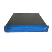
Power
Insert power cable in Standard IEC socket at rear of unit. Its hardware switch must be turned on for
unit to operate.
Audio Boards
Slots are numbered from the RIGHT when viewing the unit from the rear.
SX-48 uses DB-25 connectors for audio. Each type of I/O board uses a different layout of pins for its
audio signals. Please see section Pinouts below for details.
Note that cables for the Digidesign
TM
192 interface are suitable for use with SX-48.
Sync
You may connect all the sync sources at the same time, and choose from time to time which one to
use. The following connectors are used:
• Video Sync – BNC
• Word Clock – BNC
• AES sync – XLR
• TSCP – BNC
All connectors are labeled. Pinouts for these connectors can be found in Chapter 4 – Pinouts, page 15.
User Interface
The following guide explains how to get the unit running once it has been mounted in the rack, and
all connections made to it.
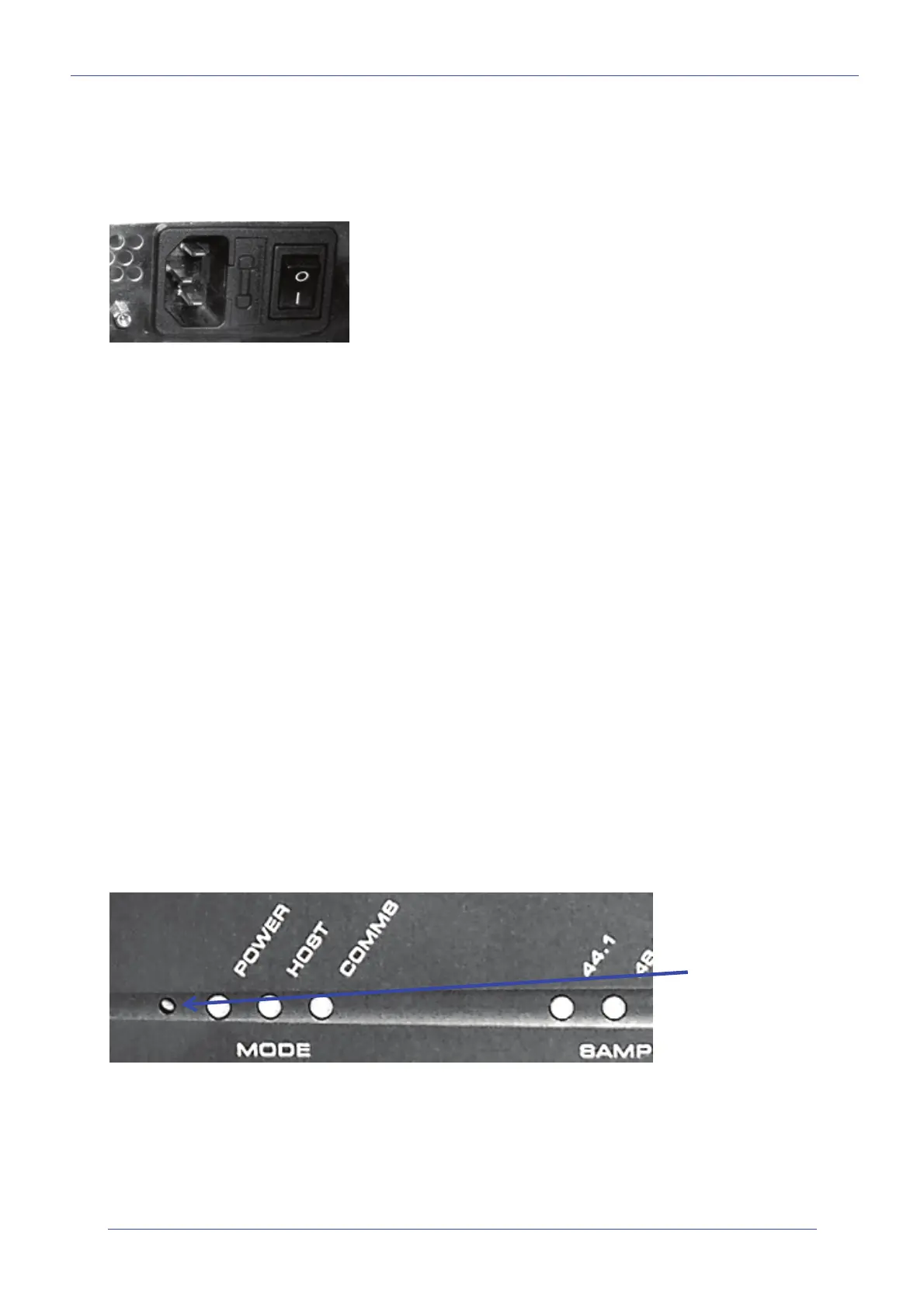
Factory Reset
Perform a Factory Reset when FIRST commissioning the SX-48. It is rarely necessary later.
Use a screwdriver or similar tool to press and hold the Setup button while powering up the unit (at the
front left). Hold it pressed for a few seconds, until LEDs on the front panel are lit.
This resets the patching and Ethernet IP address of the unit to factory standard settings.
Multiple voltages are supported: (100V,
110V, 230V or 240V
at 50 or 60 Hz)
Setup button is
behind this hole in
the metal.