64
Traffic-Control
EN
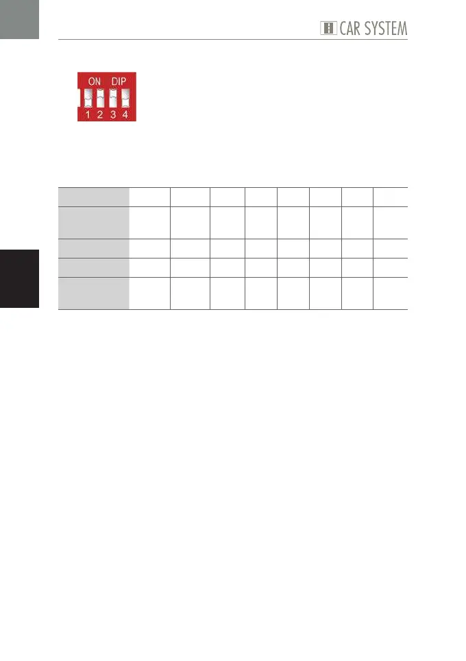
Program 7
Fig. 12: DIP configuration Program 7
This program allows to switch all eight outputs for a predefined period of
time, using the corresponding input. Programs 6 and 7 merely differ as to
the diverse activation periods used.
Possible use X 1 X 2 X 3 X 4 X 5 X 6 X 7 X 8
Sensor at
input
E1 E2 E3 E4 E5 E6 E7 E8
activates K K K K K K K K
at output A1 A2 A3 A4 A5 A6 A7 A8
for the
period of
Poti 1 Poti 2 1 s 1 s 10 s 20 s 30 s 40 s
Table 12: Program 7
X
Set the DIP as required, see Fig. 12.
X
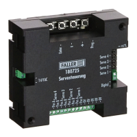
Connect the components, see Table 12.
X
If necessary, set the desired period using the potentiometers.