9.2. Setup registers
Holding registers are used to store and display instrument configuration
settings. All holding registers not listed in the table below should be considered as
reserved for manufacturer use and no attempt should be made to modify their
values. The holding register parameters may be viewed or changed using the Modbus
Protocol. Each parameter is held in two consecutive 4X registers. Modbus Protocol Function
Code 03 is used to read the parameter and Function Code 16 is used to write. Write to
only one parameter per message. Write to only one parameter per message.
Register
Address
(Dec/Hex)
Parameter Description Mode
0 / 00 r
Demand
Time
Read minutes into first demand calculation.
When the Demand Time reaches the
Demand Period then the demand values
are valid.
2 / 02 r/w
10 / 0A r/wp
12 / 0C r/w
18 / 12
r/w
Demand
Period
Write demand period: 0, 5,8, 10, 15, 20, 30
or 60 minutes, default 60. Setting the
period to 0 will cause the demand to show
the current parameter value, and demand
max to show the maximum parameter
value since last demand reset.
System
Type
Write system type: 3p4w = 3,
3p3w = 2 & 1p2w= 1
Requires password,
see parameter 13
Relay
pulse width
Write relay on period in milliseconds:
60, 100 or 200, default 200.
Network
parity
stop
Write the network port
parity/stop bits for MODBUS Protocol,
where:
0 = One stop bit and no parity, default.
1 = One stop bit and even parity.
2 = One stop bit and odd parity.
3 = Two stop bits and no parity.
Requires a restart to become effective.
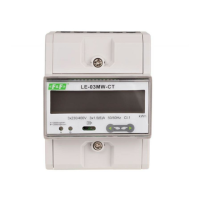
LE-03MQ CT - User manual
32
 Loading...