Chapter 11 Port Explanation
99
the plasma parameter interface (refer to section 7.3 plasma parameters), set the location
detecting time and locating up time to needed values.
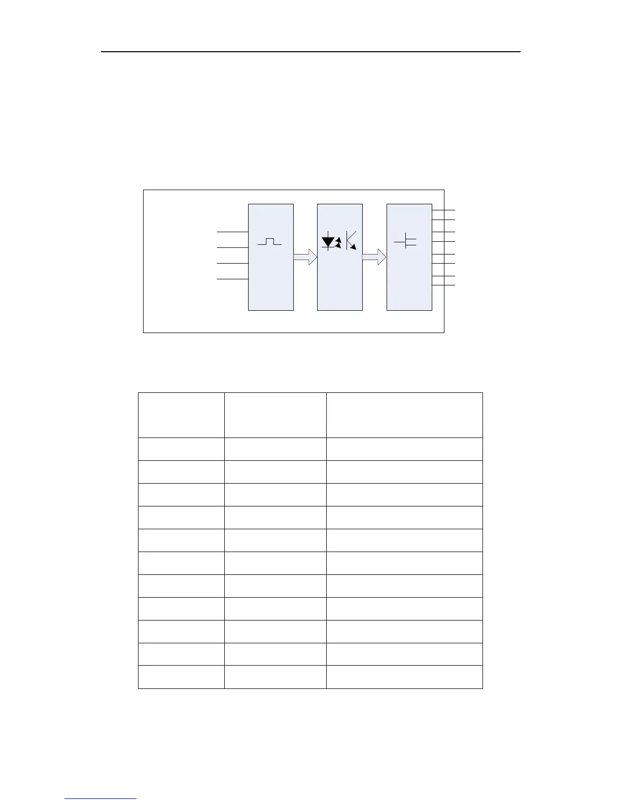
11.3 Motor Port
Signal
Shaping Photoele-
ctric
isolation
Different-
ial output
X
Y+
Y-
XDIR/XPWM-
XPWM+
YDIR/YPWM-
YPWM+
XDIR+
XDIR-
YDIR+
YDIR-
XCP+
XCP-
YCP+
YCP-
System
Fig11.8 motor port schematic diagram
Signal definition table
Number of the 15
pin interface
signal Remarks
1 XDIR+ Positive at the horizontal axis
9 XDIR- Negative at the horizontal axis
2 XCP+ Positive pulse at the horizontal axis
3 YDIR+ Positive at the vertical axis
11 YDIR- Negative at the vertical axis
4 YCP+ Positive pulse at the vertical axis
12 YCP- Negative pulse at the vertical axis
5,13,6,14 Not used
7 +5V +5V/500mA Power output
15,8 5VG 5V Power Ground