
S
Sabrina EstesAug 1, 2025
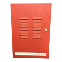
What to do if Faraday Extender outputs are not activating properly?
- DdavisbryanAug 1, 2025
To troubleshoot improper activation of the outputs on your Faraday Extender, verify that the reset switch SW2 was pressed after any changes to the DIP switch settings. Also, ensure that the DIP switch and jumper settings are correctly configured for your specific application. Confirm that the inputs are activating as expected and that the correct type of notification appliances (Conventional or Sync Strobes/Horns) are connected.