149
(MT11 - Gb2012)
XYHF
33
XYHF
44
FHYX
FHYX
FHY X
22
FHY X
11
3
"
4
/
1
83
25
4
"
16
/
13
122
1
2
"
16
/
11
68
"
4+1
INTERCOMS *
7+1
VIDEOINTERCOMS
INSTALLATION INSTRUCTIONS
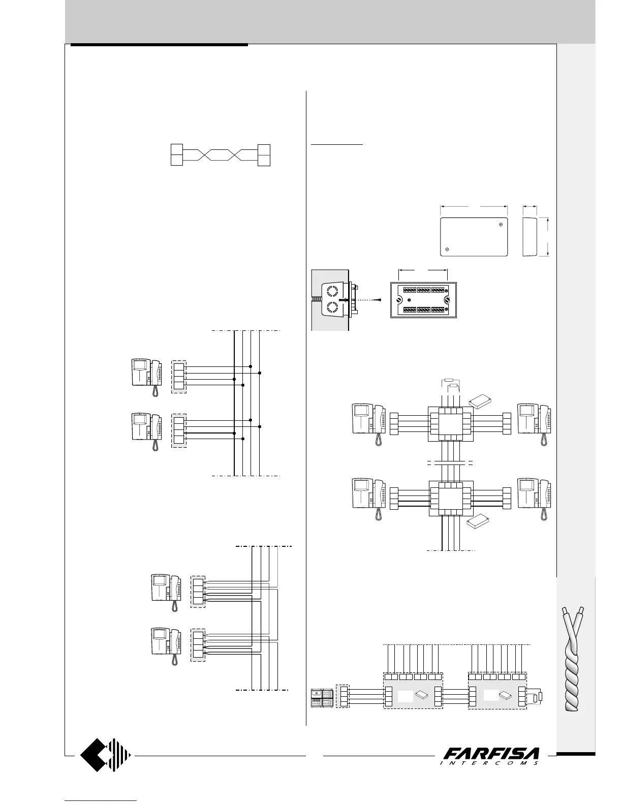
VIDEO SIGNAL DISTRIBUTION WITH TWISTED PAIR
For the connection of the video signal you can choose from:
- connection with junction box
- serial connection (input and output)
- connection with floor distributor
CONNECTION WITH JUNCTION BOX
All wires are distributed in the floor junction box.
Due to the signal loss introduced by each connection, the maximum
number of video intercoms that can be connected in shunted mode is
20. Two 75Ω resistances must be inserted between X and F and
between Y and F in the last video intercom. The maximum distance
between the video intercoms and the connector block is 2.5 metres.
CONNECTION WITH FLOOR DISTRIBUTOR
The video wires of each video intercom are insulated from the riser.
Connections are made on the DV2D or DV4D floor video signal
distributor box.
Technical data
Power supply 15÷21Vdc
Operating current 60mA
Max. input video signal 2Vpp
Insertion loss 0.8dB
Bandwidth >5MHz
Connection of the video signal with distribution on several risers
In video systems with different risers you must user 1 or more video
distributors art. DV2D or DV4D.
Terminals X and Y of the last distributor must be terminated with the 75Ω
resistances supplied with the article. It is not necessary to terminate the
unused outputs.
Example of connection on 8 risers
DV2D-DV4D. FLOOR VIDEO SIGNAL DISTRIBUTORS.
They allow for the distribution of the video signal taken from the riser on
2 or 4 outputs. They can be installed on the wall on a wall box, with
expansion plugs or it can be placed in the junction box.
Connection of the video signal on a single riser
Terminals X and Y of the last distributor must be terminated with the 75Ω
resistances supplied with the article. It is not necessary to terminate the
unused outputs.
If the distance between the camera and the last video intercom in the
system is lower than 200 m, the connection can be made with
2x0.35mm² wires (Ø=0,6mm) instead of the coaxial cable. For dis-
tances from 100m to 200m a twisted pair must be used.
SERIAL CONNECTION
Connections are made on the video intercom brackets, and not in the
junction box. Due to the signal loss introduced by each connection, the
maximum number of video intercoms that can be connected in serial
mode is 20. Two 75Ω resistances must be inserted between X and F
and between Y and F in the last video intercom.
X
Y
H
F
X
Y
H
F
ST7100
ST7100
X
Y
H
F
X
Y
H
F
ST7100
ST7100
DV2D
DV4D
DV2D
DV4D
“A” “B” “C” “D” “E” “F” “G” “H”
X
Y
H
F
X
Y
H
F
X
Y
H
F
X
Y
H
F
X
Y
H
F
X1 X1
X1
Y1 Y1
Y1
X2 X2Y2 Y2X3 X4 X3Y3 Y4 Y3 X4 Y4
2x
75W
MD41D