216
(MT11 - Gb2012)
Si 47MO/1
4+1
INTERCOMS *
7+1
VIDEOINTERCOMS
VIDEO INTERCOM SYSTEM WITH SECONDARY VIDEO STATIONS AND 2 MAIN COMMON VIDEO STATIONS
(multiple entrance)
INTERNAL STATIONS
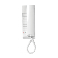
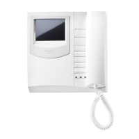
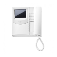
ECHOS series EXHITO series COMPACT series STUDIO series
... EH9100CT/CW ... EX3100C ... KM8100W ... ST7100CW
EH9160CT/CW EX3160C KM8600W ST7100W
... 9083 EX3160 KM8800W ... ST720W
... WA9100T/W ... WB3160 ... WB8600 ... WB7100
... TA9160 ... TA3160 ... 8083 ... WB700
... TA7100
... TA700
EXTERNAL DOOR STATIONS
PROFILO series MATRIX series MODY series
... PL71÷PL73 ... MA71÷MA73 ... MD72÷MD74
2+X PL81÷PL89 ... MAS61÷MAS63 (
1
) 2+X MD82÷MD812
2+X PL91÷PL99 * 2+X MA91÷MA93 * 2+X MD92÷MD912 *
2+X PL40PC÷PL42PC 2+X MAS42C-MAS43C 2+X MD10÷MD124
PL40P÷PL42P MAS42-MAS43 2+X MD41
... PL21÷PL228 ... MAS22-MAS24 2+X MD30
... PL20, PL50 ... MAS20 ... MD21÷MD228
... MD20, MD50
VARIOUS ARTICLES
... DV2-DV4 Video distributors
2+X 1281 Power supply
1+X 1282E Timer
2xX 1273TV Exchanger
2+... 476 Video distributor-amplifier
1 1471 Relay unit
2+X PA ** Door release button (optional)
2+X SE ** Electric door lock (12Vac-1A)
2 D ** 100V-1A diodes (type 1N4007)
common of buttons 1 and
2
to separate the common
of buttons cut here
common of buttons 3 and
4
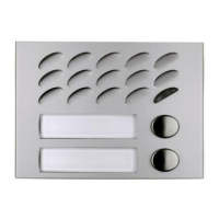
The main entrance push-button panels must
have separate common terminals. One common
terminal for each secondary door station. Buttons of
the Mody series can be divided into 2-button groups.
The common terminals of push-buttons Profilo and
Matrix series can be separated only module by
module.
Mody series button module
... Refers to number of users.
X Refers to number of secondary door stations.
(
1
) Or MA61÷MA63.
* The rain shelter is used in the place of the back box and hood cover.
** Articles not supplied by ACI Farfisa.
Working instructions.
As the basic system described on page 218, with the following variations:
- The audio-video functions and door lock opening are automatically switched to the door
station which has made the call (or control switching ON) and remain in this state until
a call from another entrance is received.
- Services to secondary door stations are independent and can be operated at the same
time.
Notes
- For audio compatibility we do not suggest to connect door stations MODY series with
internal devices ECHOS series.
- If the control switching ON is necessary, connect terminal 4 of the timer (dashed wire).
- For the connection of name plate lamps read notes 6, 7 and 8 of the installation
instructions on page 146.
- For wires dimensioning and video connection refer to the installation instructions and
table on pages 146÷148.
- For other types of push-button panels see the general catalogue.
Connection of 1281E power supply-timer in-
stead of 1281 plus 1282E.
By adding 1281E to the schematics on page 217
instead of 1281 plus 1282E, the system working will
modify as follows:
- switching-OFF at the end of the timing only.
230V
127V
0
1281E
F
SH3+ X 5
C+
4
Power supply-timer of the secondary entrance
Power supply-timer of the main entrance
230V
127V
0
1281E
5
C+
X
H
F
S3+
A
4
DS1 is a diagram reference
Control switching ON deactivation
To deactivate the monitoring function
during the conversation and to keep it
only when the system is in standby, it is
necessary to install a relay (type 1471 or
1472) and connect it as shown on the
diagram.
to the video-
intercoms
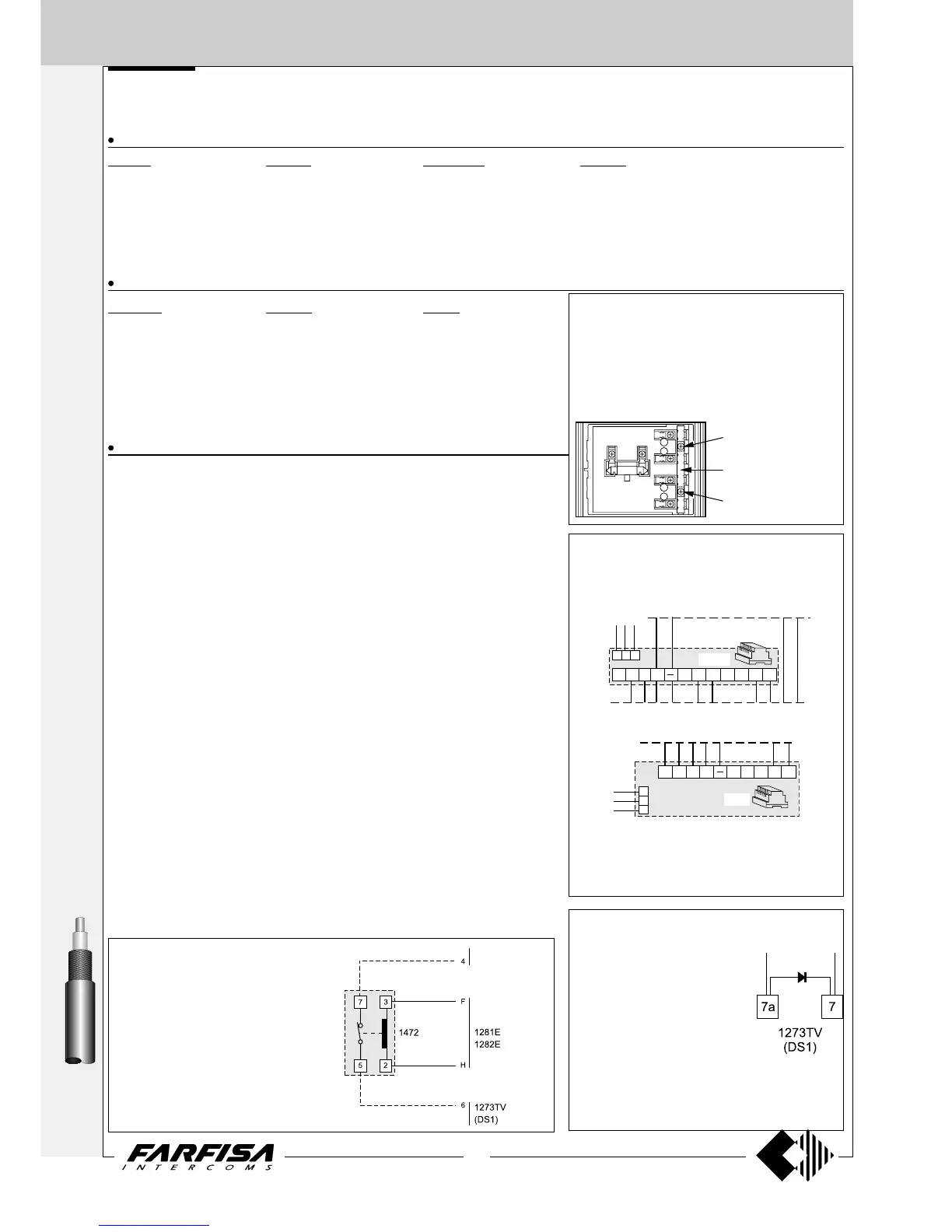
Connection of two door locks, of which the
secondary is always activable, in a system with
multiple entrance
For this option it is necessary to
install a diode (100V-1A; type
1N4007) between terminals 7
(cathode) and 7a (anode) of every
secondary exchanger. The diode
allows to activate also the door
look of your own entrance when the
door look of the main entrance is activated. On the
contrary when the door lock of your own entrance is
activated the door look of the main entrance is not
activated.