220
(MT11 - Gb2012)
4+1
INTERCOMS *
7+1
VIDEOINTERCOMS
Extension of ONE-WAY system
To realise a one-way system with several monitors and/or
intercoms in parallel, with or without intercommunicating
service, you must proceed as follows:
- make a photocopy of the additional diagram desired, select-
ing it among those of pages 222, 223, 224, 226 and 227;
- place the diagram on the basic diagram so as to cover the
existing video intercom and line up the wires of the two
diagrams;
- if specified in the additional diagram, connect the wires I and
C (common terminal of additional buttons) to terminals IV and
7 of art. 1282E;
- to obtain the intercommunicating service, make the connec-
tions which have been drawn with a dashed line, install the
1443E module inside timer 1282E and move the jumper J1
of the videointercom bracket from position 2-3 to 1-2.
Example (see page 219): by making a photocopy of the
additional diagram of page 224 (2 video intercoms and 1
intercom in parallel with or without intercommunicating serv-
ice), placing it on the installation diagram of page 197 (Si
42MO/1), lining it up to the wires of the first video intercom and
eliminating the second video intercom and the video distribu-
tor, it is possible to obtain a one-way system with 2 video
intercoms and 1 intercom in parallel connected to 2 external
video stations.
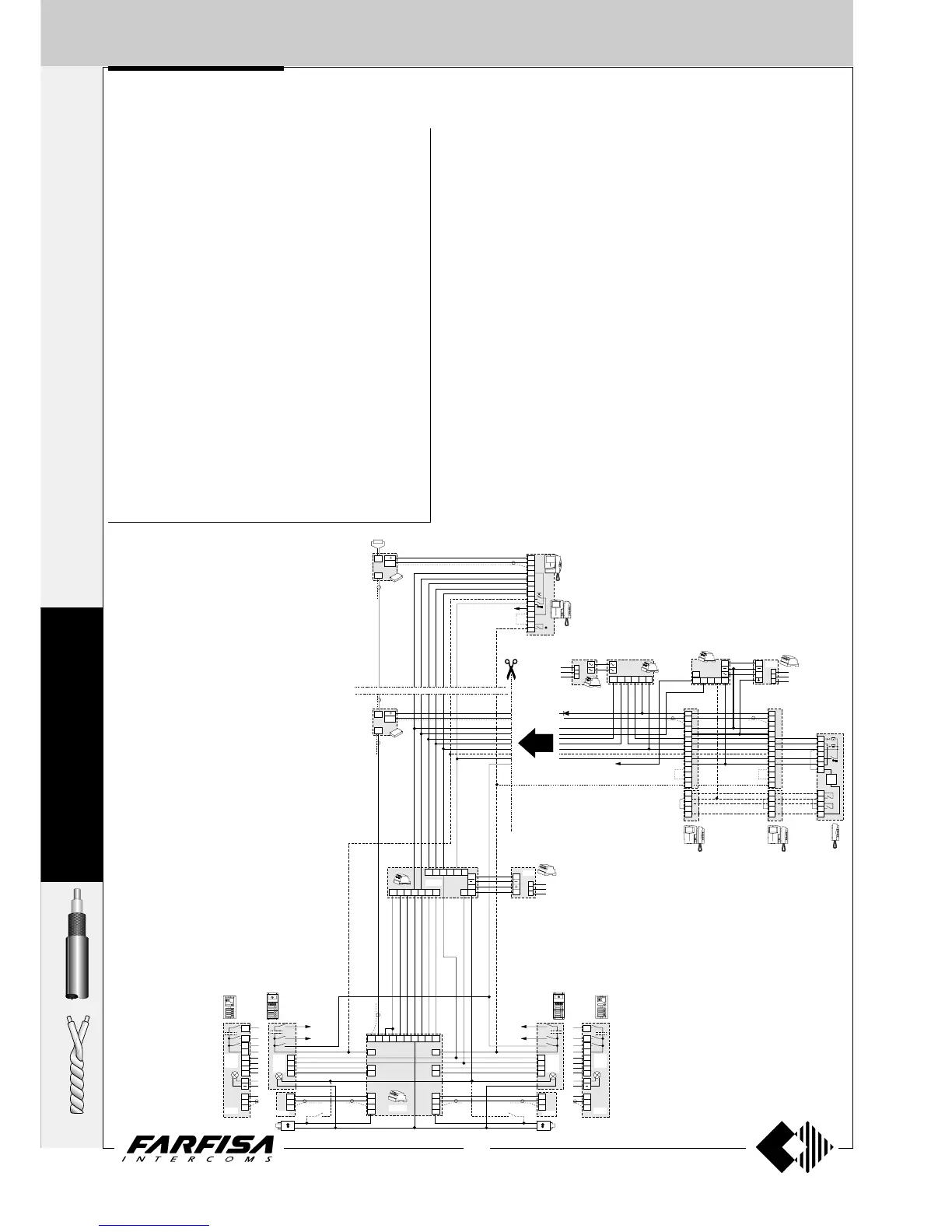
EXTENSION OF VIDEO INTERCOM SYSTEM
Additional diagrams
Extension in one apartment of a MULTI-WAY system
To realise a multi-way system with several video intercoms and/or intercoms in
parallel in one apartment with or without intercommunicating service, you
must proceed as follows:
- make a photocopy of the additional diagram desired, selecting it among those
of pages 223, 225, 228 and 229;
- place the diagram on the basic diagram so as to cover the existing video
intercom and line up the wires of the two diagrams;
- to obtain the intercommunicating service, make the connections which have
been drawn with a dashed line and move the jumper J1 of the videointercom
bracket from position 2-3 to 1-2.
Example: by making a photocopy of the additional diagram of page 224 (2
videointercoms and 1 intercom in parallel with or without intercommunicating
service), placing it on the installation diagram of page 197 (Si 42MO/1), lining it
up to the wires of the first video intercom, it is possible to obtain a multi-way
system with 2 video intercoms and 1 intercom in parallel in one apartment and
intercommunicating connected to 2 external video stations.
Extension of a MULTI-WAY system in several apartments
To realise a multi-way system with several video intercoms and/or intercoms in
parallel in 2 or more apartments with or without intercommunicating service,
you must repeat the operations described in the preceding section several times.
OUT
OUT
PA
PA
SESE
IN
IN
IN
75W
DV2
DV4
DV2
DV4
230V
127V
0
1282E
4
3
2
1
2D1D 3D
5
7
xnxn
x2x2
1281
MD1.
MD2.
MD30
MD7.
MD1.
MD2.
MD30
MD7.
MD41MD41
4
IN
I
A
H
V
M
H
V
M
4
3
2
1
4
3
2
1
PP
PP
PP
CC
AA
Mody
Mody
Matrix
Matrix
MA4.MA4.
MA2.
MA6.
MA7.
MA2.
MA6.
MA7.
IV
H
A
3+
10a
9a
8a
7a
12b
11b
36
1273TV
H
V
M
H
V
M
10b
9b
8b
7b
4
3
2
1
12a
11a
F
X
1
2
H
SC+
xn
ST7100+WB7100
+ST720+WB700
KM8100+WB8600
KM8600+WB8600+8083
KM8800+WB8600
8
V
M
F
H
1
2
3
4
5
9M
PC
P
1C
9R
121110217
5
498
RL37
9R
79M
H
B
9P
CT1
ST720+
ST701+
ST704
VC1 VC2
ST7100+
WB7100+
ST720+
WB700+
ST701
ST7100+
WB7100+
ST720+
WB700+
ST701
9
C
P1
C
P2
9
C
P1
C
P2
230V
127V
0
1281
Xn
D
ST
704
1
2
P1
C
P2
C
9A
2443
230V
127V
0
PRS210
1412
13a
12a
13
F
1
2
3
5
9
3A
8
V
M
F
H
1
2
3
4
5
9M
PC
P
1C
9R
8
V
M
F
H
1
2
3
4
5
9M
PC
P
1C
9R
IV
A
I
To terminal P of the video inter-
coms. It is also necessary to con-
nect 1C and PC.
Example of combination of an addi-
tional diagram with a basic diagram
for the realisation of a multi-way sys-
tem with extension in one apartment
only.