Do you have a question about the FATEK FBs-CM25 and is the answer not in the manual?
Details serial communication connectors for specific FBs-CM models.
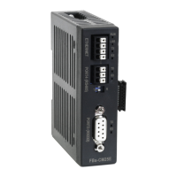
Outlines the characteristics and description of the Ethernet serial interface.
Describes the Euro 4-pin plug connector for Ethernet.
Details the signals for the port4 connector, which is RS485 level.
Explains the port3 connector's signal levels (RS232 or RS485).
Explains the function of network status indicators like LINK, RX, TX.
Explains the function of serial port status indicators like RX, TX.
Describes the function of the Port3 connector as a general communication port.
Explains Port4's function for Ethernet signal coupling and as a general communication port.
Presents two operating modes: Server Mode and Client Mode.
Details how the module operates in Server Mode, waiting for network messages.
Illustrates server mode application with multiple PLCs connected via RS485.
Explains how the module operates in Client Mode, waiting for serial port messages.
Describes the standard client mode where master PLC sends commands to other PLCs.
Details the virtual server mode for balancing security and connectivity.
Explains how to set DIP switches for termination resistor installation and password protection.
Provides details on serial and network cable wiring.
Introduces the 'Ether_cfg.exe' software and its basic functions.
Covers setting IP, gateway, netmask, baud rate, and operating mode.
Explains setting authorized IP addresses to secure the system.
Describes mapping local stations to remote stations for network transparency.
Details the most convenient method for network configuration via LAN.
Explains how to configure network settings via the Internet.
Step-by-step guide for configuring the module via a local area network.
Step-by-step guide for configuring the module via the Internet.
Details how to set common data parameters for the Ethernet module.
Explains security measures like password protection and remote configuration.
Explains how to set authorized IP addresses to prevent illegal access.
Details setting up station and IP mapping for client mode.
Defines the station number of the local PLC.
Defines the station number of the remote PLC.
Defines the IP address of the remote Ethernet module.
Defines the group size for station mapping.
Explains setting service port numbers for TCP/UDP server modes.
Describes how to update the Ethernet module's configuration.
Details the pinout and flow for the RS232 port signal.
Provides a signal diagram for the RS485 port.
Explains the FATEK/TCP/UDP communication protocol.
Refers to the Modbus/TCP communication protocol documentation.
| Model | FBs-CM25 |
|---|---|
| Type | Control Unit |
| Input Voltage | 24V DC |
| Communication Ports | RS-232, RS-485, Ethernet |
| Power Supply | 24V DC |
| Number of Digital Inputs | 16 |
| Number of Digital Outputs | 16 |
| Weight | 0.5 kg |
| Programming Language | Ladder Diagram |
| Protocols Supported | Modbus |
| Operating Temperature | 0°C to 55°C |
| Storage Temperature | -20°C to 70°C |
| Humidity | 5% to 95% (non-condensing) |