4
3. Outline
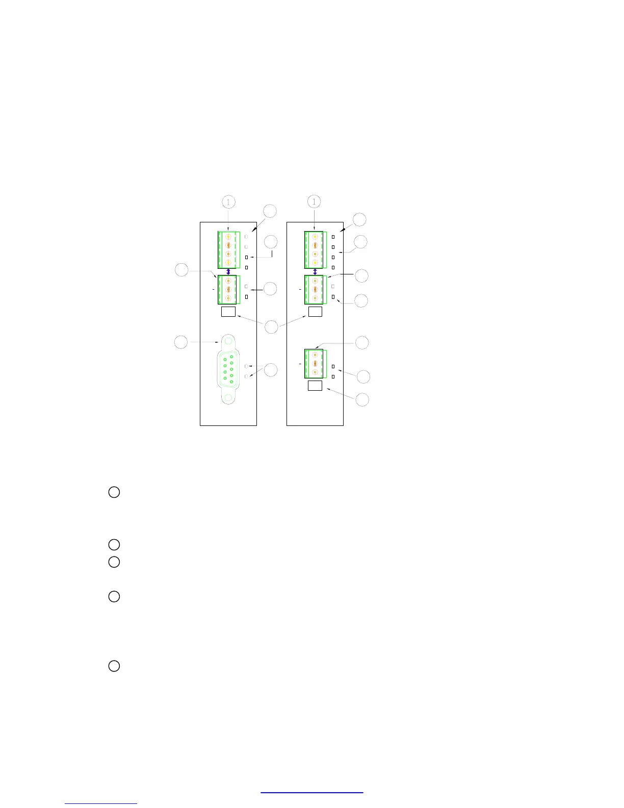
The outline of FBs-CM25E/CM55E module is shown below
8
FBs-CM25E FBs-CM55E
2
++
PORT4 (RS485)
PORT4 (RS485)
PORT3 (RS232)
3
7
RX
TX
T
G
N
6
RX
TX
5
PORT3 (RS485)
T
G
N
RX
+
TX
7
3
TN
G
RX
TX
5
ETHERNET
2
2
1
3
6
RX
TX
RUN
LNK
4
LNK
RUN
ETHERNET
2
1
RX
TX
3
6
4
9
9
and described at follow:
1 Ethernet connector: To meet the anti-vibration requirement of industrial
environment, instead of using regular RJ-45 connector but using Euro. 4 pin
plug connector.
2 port4 connector: The signals in this connector is RS485 level.
3 port3 connector: The signals in this connector can be RS232(CM25E) or
RS485(CM55E). This port is a general purpose communication port
4 Network indicators:
LINK: Lit, when the Ethernet cable is properly working.
RX: Lit, when detecting a signal activity of the Ethernet.
TX: Lit, when the module is sending a message into the Ethernet.
5 Serial port status indicators:
RX: Lit, when detecting a signal activity of the serial port.
TX: Lit, when the module is sending a message into the serial port.