37X INSTALLATION & OPERATION MANUAL
372/373 MODEL
40
12. DIAGRAMS AND SCHEMATICS
12.1 Mounting Templates
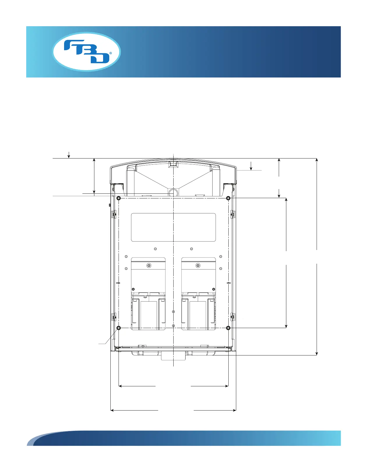
To permanently secure the dispenser to a countertop, use the provided mounting diagrams (Figures 12.1 and 12.2) to
drill 7/16” clearance holes into the countertop. Next, place the dispenser in position and install 3/8”-16 UNC bolts from
the underside of the countertop into the threaded bosses in the frame. Seal the dispenser to the countertop with a bead
of clear silicone caulk around the base of the frame to prevent spills from collecting under the dispenser.
16.13 in.
[409.58 mm]
25.70 in.
[652.80 mm]
3.49 in.
[88.52 mm]
13.63 in.
[346.08 mm]
15.62 in.
[396.80 mm]
(4) 3/8-16
TAPPED HOLES
(CLEARANCE HOLE)
4.74 in.
[120.31 mm]
DRIP TRAY
3.39 in.
[86.14 mm]
DRAIN
4.41 in.
[112.01 mm]
Figure 12.1 372 Mounting Diagram