BIB SUPPLY
A. Fabricate the appropriate number of 3/8 inch supply lines for connecting the unit to the syrup
pumps.
B. Connect the syrup lines to the bulkhead fittings as follows:
1. For the FBD562 Unit - to the appropriate bulkhead syrup fittings located at the rear of the unit
(see Figure 5.2).
2. For the FBD563 Unit - to the appropriate bulkhead syrup fittings located at the rear of the unit
(see Figure 5.3).
3. For the FBD564 Unit - to the appropriate bulkhead syrup fittings located at the rear of the unit
(see Figure 5.4).
C. Do not turn on the CO2 at this time.
FIVE GALLON (FIGAL) TANK SUPPLY
A. Fabricate the appropriate number of 3/8 inch supply lines for connecting the unit to the syrup
tanks.
B. Connect the syrup lines to the bulkhead fittings as follows:
1. For the FBD562 Unit - to bulkhead fittings labeled “SYRUP LEFT” and “SYRUP RIGHT” located
at the rear of the unit (see Figure 5.2).
2. For the FBD563 Unit - to bulkhead fittings labeled “SYRUP LEFT”, “SYRUP CENTER”, and
“SYRUP RIGHT” located at the rear of the unit (see Figure 5.3).
3. For the FBD564 Unit - to bulkhead fittings labeled “FLAVOR #1”, “FLAVOR #2”, “FLAVOR #3”,
and “FLAVOR #4” located at the rear of the unit (see Figure 5.4).
C. When using five gallon (figal) syrup tanks, a Syrup Restart Valve (SRV) and tank couplers
must be used on each line. Warranties will be void if an SRV is not installed.
1. The “OUT OF” devices in the machine will not function properly without the use of a Syrup
Restart Valve. If the “OUT OF” devices do not function, the machine will supply only water to
the product cylinder and it will freeze up.
2. When replacing a figal, insure that the syrup line to the dispenser is attached to the figal before
the CO2 line is attached to the figal. This will allow the SRV to work properly.
3. To operate the SRV, press the restart button
after syrup tank is changed. The red light
beside each chamber will then go out and
product will refreeze.
D. Do not turn on the CO2 at this time.
11
6. STARTING THE UNIT
6.1 INITIAL POWER-UP
A. Insure the electrical power is disconnected from
the unit.
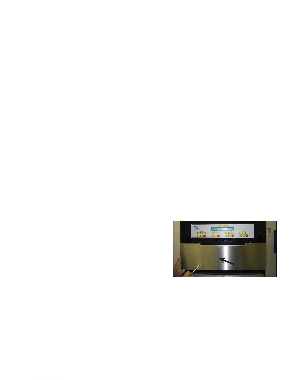
B. Using a Phillips head screwdriver, remove the
stainless steel access panel located below the
keypad (see Figure 6.1).
C. Remove the splash plate and electric box cover
(see Figure 6.2).
D. Plug unit in to the electrical power. The graphics display should illuminate. Check for the display of
information on the LCD control panel (this will read “COPYRIGHT” on bottom line of LCD display).
E. With voltage meter, check voltage at contactor between L1 & L2 and record (see Figure 6.3 and the
applicable Upper Board schematic in Section 14).
F. Access the “Line Voltage” readout in the “SERVICE MENU\READOUTS\COMMON
READOUTS” section of the LCD menu. If the “Readout” voltage is more than two (2) volts
different than the voltage across L1 and L2, the “Voltage Offset” must be changed.
Failure to do so will cause performance loss of the unit. To change the “voltage offset”, go to
“SERVICE MENU\MACHINE SETTINGS\COMMON SETTINGS” and enter the difference between
the meter reading and the “Line Voltage” readout to make the LCD voltage reading match the L1 and
L2 voltage. Reinstall the splash plate and electric box cover.
Access Panel
Typical Access Panel
Figure 6.1