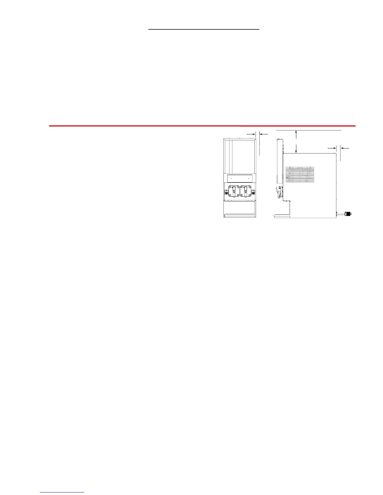
1. Removal of side panels, if service is necessary.
2. Air circulation around vents on sides, back, and top of unit.
C. A well-ventilated room is required with a temperature of 50°F to 90°F (10°C to 32.5°C). The
environment, however, should be stable and not subject to abrupt changes in temperature.
D. The unit should not be exposed to direct sunlight or chemicals.
1.2 ADDITIONAL REQUIREMENTS (TO BE PROVIDED BY THE CUSTOMER)
A. CO2 supply with a pressure of 70-72 psig ( 482.6 to 496.4 kPag). If a bulk CO2 supply is
used, the pressure should be set at 115 to 120 psig (792.9 to 827.4 kPag) and a secondary
regulator installed at the unit to reduce the pressure to 70-72 psig.
B. Syrup supply - Bag-in-Box or five (5) gallon syrup tank (figal).
C. Water supply with a minimum flowing pressure of 30 psig (206.8 kPag) and a maximum static
pressure of 70 psig (482.6 kPag).
2. RECEIVING AND UNPACKING UNIT
2.1 RECEIVING
Each unit is tested and thoroughly inspected before shipment. At the time of shipment, the carrier
accepts the unit and any claim for damages must be made with the carrier. Upon receiving the unit
from the delivering carrier, carefully inspect carton for visible indication of damage. If damage exists,
have carrier note same on bill of lading and file a claim with the carrier.
2.2 UNPACKING
A. Cut banding from shipping carton and remove carton by lifting up. Remove protective side
panels and four corner protectors.
B. Remove drip tray assembly, accessory kit and manual from top packaging. Contact the dealer if
any parts are missing or damaged.
C. Remove side panels from unit.
D. Inspect unit for concealed damage. If evident, immediately notify delivering carrier and file a claim
against same.
7
12 INCHES
2 INCHES
2 INCHES
Figure 1.1
(FBD562 Unit Displayed)
TABLE OF CONTENTS (CONTINUED)
14.2 MOUNTING DIAGRAM - FBD563 ...................................................................................................43
14.3 MOUNTING DIAGRAM - FBD564 ...................................................................................................44
14.4 FLOW DIAGRAM/SCHEMATIC - FBD562 ......................................................................................45
14.5 FLOW DIAGRAM/SCHEMATIC - FBD563 ......................................................................................46
14.6 FLOW DIAGRAM/SCHEMATIC - FBD564 ......................................................................................47
14.7 UPPER BOARD SCHEMATIC - FBD562 ........................................................................................48
14.8 LOWER BOARD SCHEMATIC - FBD562 .......................................................................................49
14.9 UPPER BOARD SCHEMATIC - FBD563 ........................................................................................50
14.10 LOWER BOARD SCHEMATIC - FBD563 .....................................................................................51
14.11 UPPER BOARD SCHEMATIC - FBD564 ......................................................................................52
14.12 LOWER BOARD SCHEMATIC - FBD564 .....................................................................................53
14.13 LOWER BOARD SCHEMATIC (INCLUDES AUXILIARY BOARD AND
DIO BOARD) - FBD564 ................................................................................................................54
1. PREPARING THE LOCATION
1.1 LOCATION REQUIREMENTS
A. The operational FBD56X countertop units
range in weight from 345 pounds (156.5
kg) to 460 pounds (208.7 kg) and each
unit requires a sturdy, level surface for
placement (see Safety Precautions, page 3).
When selecting a counter location, ensure
the counter will support the unit weight
plus the weight of any additional equipment
placed near it.
B. Adequate space above and behind a unit
(See Figure 1.1) is required to allow: