Fluid Components International LLC ST75/ST75V Mass Flow Meter
This page is subject to proprietary rights statement on last page
14
06EN003368 Rev. G
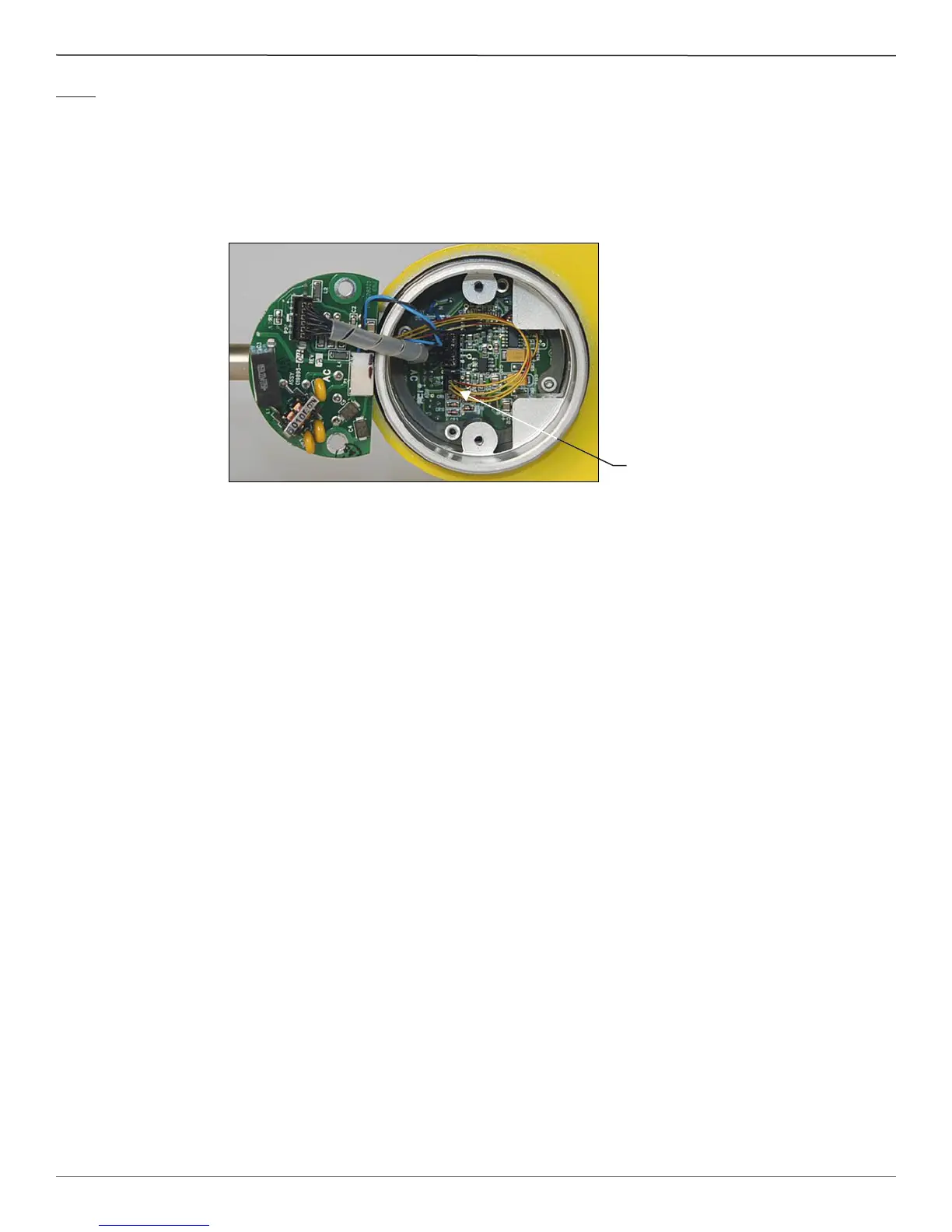
Step 3
Verify sensor element continuity and resistance.
Remove sensor element cable from the bottom of the control circuit assembly. Note that two of the wires have a red stripe and are
located closest to the interconnecting cable header. Using an ohmmeter verify that resistance between the 2 red striped wires is approx-
imately 1100 ohms ±20 ohms. This resistance is temperature dependent. The resistance at 70 degrees F is about 1082 ohms. Verify the
resistance between the 2 natural colored wires are approximately the same.
FCI provides full in-house technical support. Additional technical representation is also provided by FCI eld representatives. Before
contacting a eld or in-house representative, please perform the troubleshooting techniques outlined in this document. If problems
persist, contact the FCI Customer Service department at 1-800-854-1993 or 1-760-744-6950.
Contact FCI to obtain a Return Authorization before returning the instrument. The form contains a declaration of decontamination
cleaning information that the instrument must comply with before it is shipped to FCI.
Sensor Element
Cable