ST75/ST75V Mass Flow Meter Fluid Components International LLC
This page is subject to proprietary rights statement on last page
15
06EN003368 Rev. G
Transmitter Circuit Calibration Check (Delta R Verication)
References
• Delta ‘R’ Data Sheet
Equipment
• FC88 Communicator or equivalent.
• DVM
• Delta R data sheet - Match by serial numbers
• 2 ea. precision decade resistance boxes, 0.1% (Largest steps: 1k ohm, smallest steps 0.01 ohms)
• Small at blade screwdriver, 3/32 inches wide blade
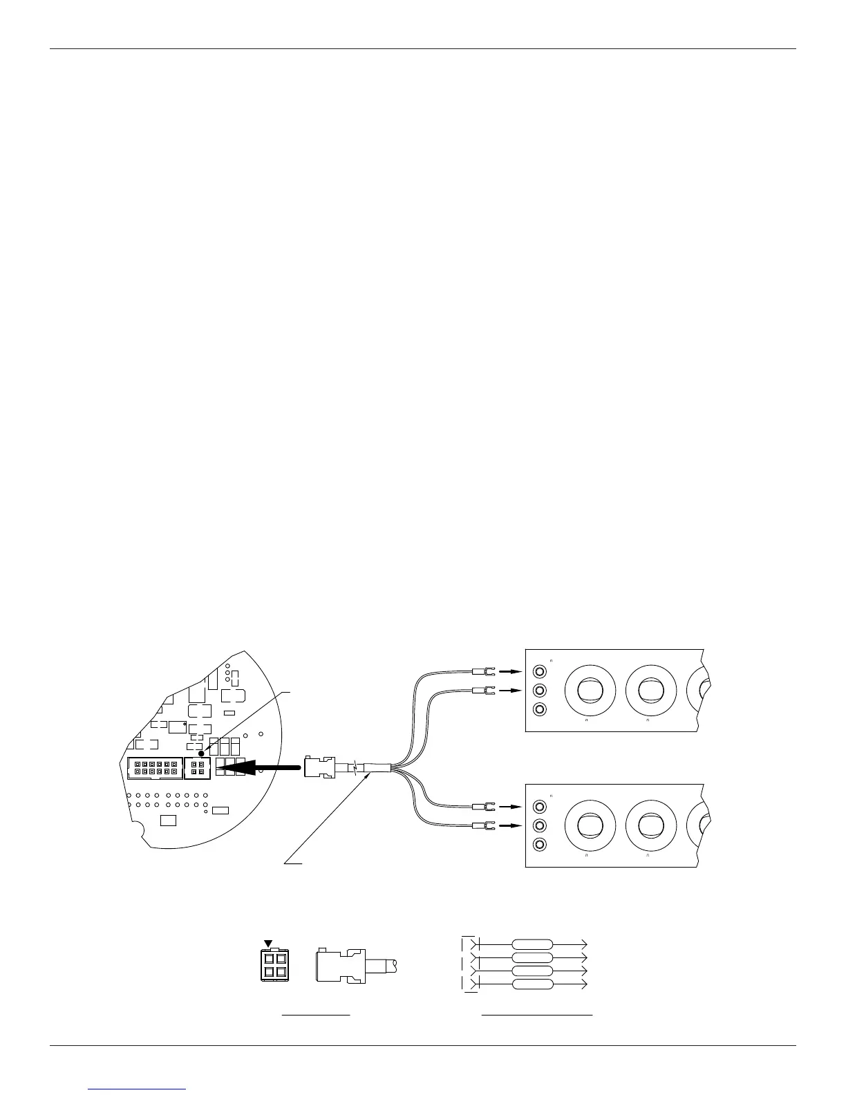
• FCI normalization cable, FCI part number 006407
Procedure
1. Verify all “D” mode calibration parameters are correct according to the meter’s Delta R data sheet before starting verication.
2. Turn power OFF.
3. Mark all sensor element wires connected to the circuit board for easier reconnection to the proper terminals. Disconnect the wires.
4. Connect the resistance decade box to the electronics as per the appropriate wiring diagram for the ST75/ST75V.
Note: Interconnecting wiring (resistance decade box to electronics) must be same gauge and length to avoid any inaccura-
cies in the Delta R verication caused by unequal wire lengths and/or wire gauges.
5. Set both decade boxes for the nominal resistance value (1000 ohms) ±0.01%
6. Connect DVM to the meter’s output termination and monitor the meter output.
7. Turn the power ON and allow the instrument 5 minutes to stabilize.
8. With the FC88 connected, Press [T] [Enter] to view the Normal Operating Mode.
9. Adjust the Active decade box (Reference decade box remains xed @ 1000 ohms) to achieve the appropriate Delta R for the
displayed ow value and output, noted on the meter’s Delta R data sheet.
10. Note the [C] mode and verify the meter’s displayed TCDR and REFR values corresponding to the displayed ow rate as per
the meter’s Delta R data sheet.
11. Return to normal mode operation ([T] mode).
REFERENCE
1433-W DECADE RESISTOR GENERAL RADIO USA
9
8
7
6
X
G
23mA MAX
1K STEPS
H
L
10
K
2
0
1
4
5
3
ACTIVE
6
8
9
X
6
7
100 STEPS
80mA MAX
2
1
0
4
3
5
2
1
4
5
3
1433-W DECADE RESISTOR GENERAL RADIO USA
X
6
7
8
9
G
1K STEPS
23mA MAX
H
L
10
K
1
0
2
4
5
3
7
6
X
9
8
6
100 STEPS
80mA MAX
0
1
2
5
3
4
1
2
4
5
3
NORMALIZATION CABLE
FCI P/N 006407
2
3
1
4
ACT 3ORANGE
3
4
CABLE WIRING SCHEMATIC
ORANGE ACT 4
2
1
BLACK
BLACK
REF 2
REF 1
PIN ONE
CABLE PIN OUTS
END VIEW SIDE VIEW
C10
GND
C1
U3
C5
CR8
CR7
CR6
U5
C12
C11
C2
PWB 019695-01
C7
J1
P1
CR3
CR10
CR9
C4
ACT
R5
V+
REV
P2
FCI
-
IN USA
MADE
REV-
AC
BLACK
BLACK
ORANGE
ORANGE
PIN ONE
INDICATOR
REF
C00933-1-2