18
!
"
#
%
& / *
BL
)
BM
BN
$
!
"
#
Edgebander
G 330 / G 360 / G 380
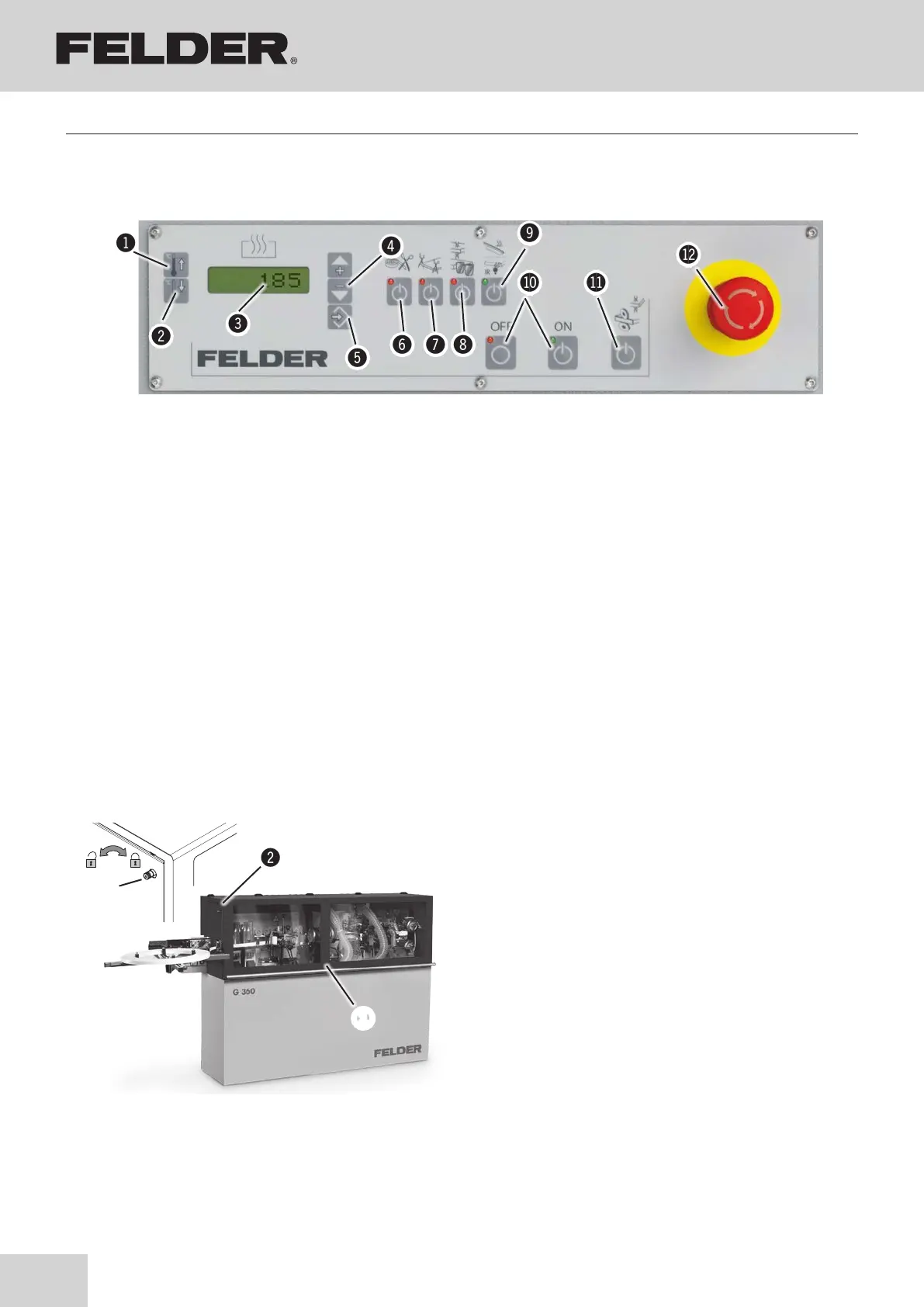
Choice switch ON/OFF:
ON / Active: LED lights up
OFF / Deactivated: Light off
& Guillotine unit
ON: Edge roller
OFF: Strip material
/ End trimming unit
( Side Trimming Unit (only G 360 / G 380)
) Heated guide ruler (only G 330)
Infrared lamp (Optional / only G 360 / G 380)
BL Start/Stop buttons for the unit
BM Buffing unit / Spraying equipment
BN EMERGENCY-STOP button
5.3 Electrical control panel - Standard equipment
Thermoregulator to control the temperature of the glue
pot with double display:
! Operating temperature (SP1)
" Stand-by temperature (SP2)
# Digital temperature indicator
$ “+” and “–” set the value desired for SP1 and SP2
% Enter key
Fig. 5-3: Electrical control panel
Assembly
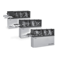
5.4 Safety devices - Safety break switches
Fig. 5-4: Safety break switches - hinged lid
!hinged lid
ŠSafety break switches
#Thumb screw
Your machine is equipped with safety break switches.
The machine will only operate if the break switches,
inside the machine frame, are actuated by the locking
system of the hinged lids.
This hinged lid may only be opened once the machine is
in the idle mode.
Prepare the machine to operate:
1. Close the cover on the back of the machine.
2. Tighten the thumb screw.
(Clockwise - up to stop)
Open the cover on the back of the machine:
1. Switch the machine off and ensure that it cannot be
switched on again.
2. Loosen the thumb screw.
(Anti-clockwise - up to stop)