Page 4
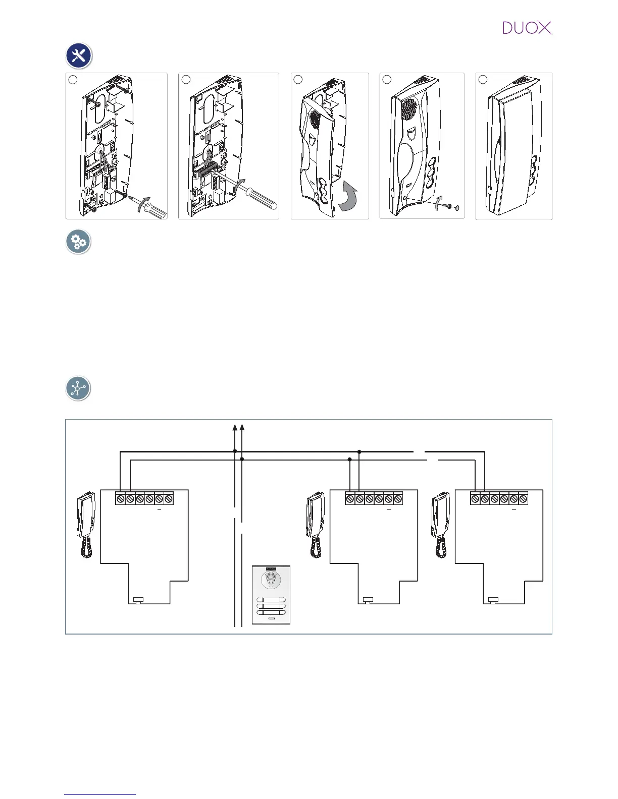
CONNECTIONS
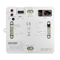
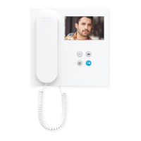
B, B : Bus DUOX: Power, data and audio .
T, -: Connection House entrance „door bell.“ (P1).
A, -: Call extension connection or light and bell activator.
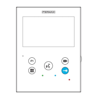
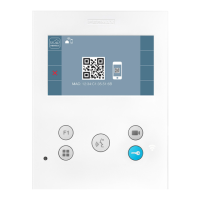
F1: Button for additional functions. It provides a negative upon being activated.
You will fi nd
more details in „LOFT Telephone Operation - Auxiliary function F1“.
Connection
DIAGRAMS
TELEPHONE Installation
Wiring: 2 non-polarised wires.
B
B
B
B
SW5
A
B B T
F1
SW5
A
B B T
F1
SW5
A
B B T
F1
P1 (T, -): You can place an external button to make a call to the „Door bell“ (this bell would
replace the ding-dong of the home entrance).
Notes:
- The doorbell can not be changed and is different from those selected for entry panels or
guard unit.
- The do not disturb function silences this tone.
- You can program the phone´s address with this button. See chapter: Programming the phones
address via the doorbell.