BLUEHELIX TECH RRT 24 C
10 EN
cod. 3541P250 - Rev. 01 - 07/2018
2.2 Place of installation
The combustion circuit is sealed with respect to the
place of installation and therefore the unit can be in-
stalled in any room. However, the place of installation
must be sufficiently ventilated to prevent the creation
of dangerous conditions in case of even slight gas
leaks. This safety regulation is provided for by EEC Di-
rective no. 90/396 for all gas units, including those with
a sealed chamber.
In any case, the place of installation must be free of dust,
flammable materials or objects or corrosive gases.
The boiler is arranged for wall mounting and comes
standard with a hanging bracket. A paper template for
marking the drilling points on the wall is provided in the
box. The wall fixing must ensure stable and effective
support for the boiler.
A
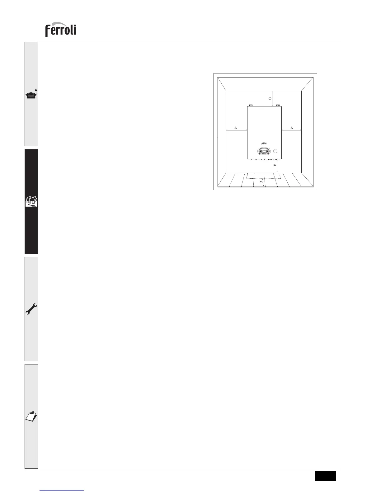
If the unit is enclosed in a cabinet or mounted
alongside, a space must be provided for re-
moving the casing and for normal mainte-
nance operations. The minimum
measurements to be respected are given in
fig. 17.
fig. 17 - Minimum distances around the boiler
A Min. 2,5 cm
B Min. 20 cm
C Min. 30 cm
D Min. 60 cm (via an openable panel)
2.3 Plumbing connections
Important
The heating capacity of the boiler must be previously established by calculating the building's heat requirement according
to the current regulations. To ensure proper operation and long boiler life, the plumbing system must be adequately sized
and complete with all the necessary accessories, including a room thermostat, a thermostatic radiator valve (TRV), etc.
The system flow and return pipes must have a diameter of at least 22 mm for the first 3 m of length from the unit.
If the system delivery and return pipes follow a path where air pockets could form in certain places, it is advisable to
install vent valves at these points. Also, install type "A" drain cocks at the lowest points in the system to allow complete
emptying.
The temperature drop between the delivery manifold and the return to the boiler should not exceed 20 °C.
A flow rate of at least 6 litres/min through the heat exchanger is required.
B
Do not use the water system pipes to earth electrical appliances.
Before installation, carefully
flush all the heating system pipes to remove any residuals or impurities that could affect
proper operation of the unit (as required by BS 7593 Building regs Doc L).
B
The safety valve discharge must be connected to a 15 mm diameter copper pipe descending from the boiler
to run off system water in case of overpressure in the heating circuit. Otherwise, the boiler manufacturer
cannot be held liable if the discharge valve operates and floods the room
. The discharge must be run
to the outside of the building to prevent the risk of damage or injury caused by discharged hot water in case
of overpressure in the system.

 Loading...