SUN P7
51
Cod. 3540I810 - 03/2009 (Rev. 00)
EN
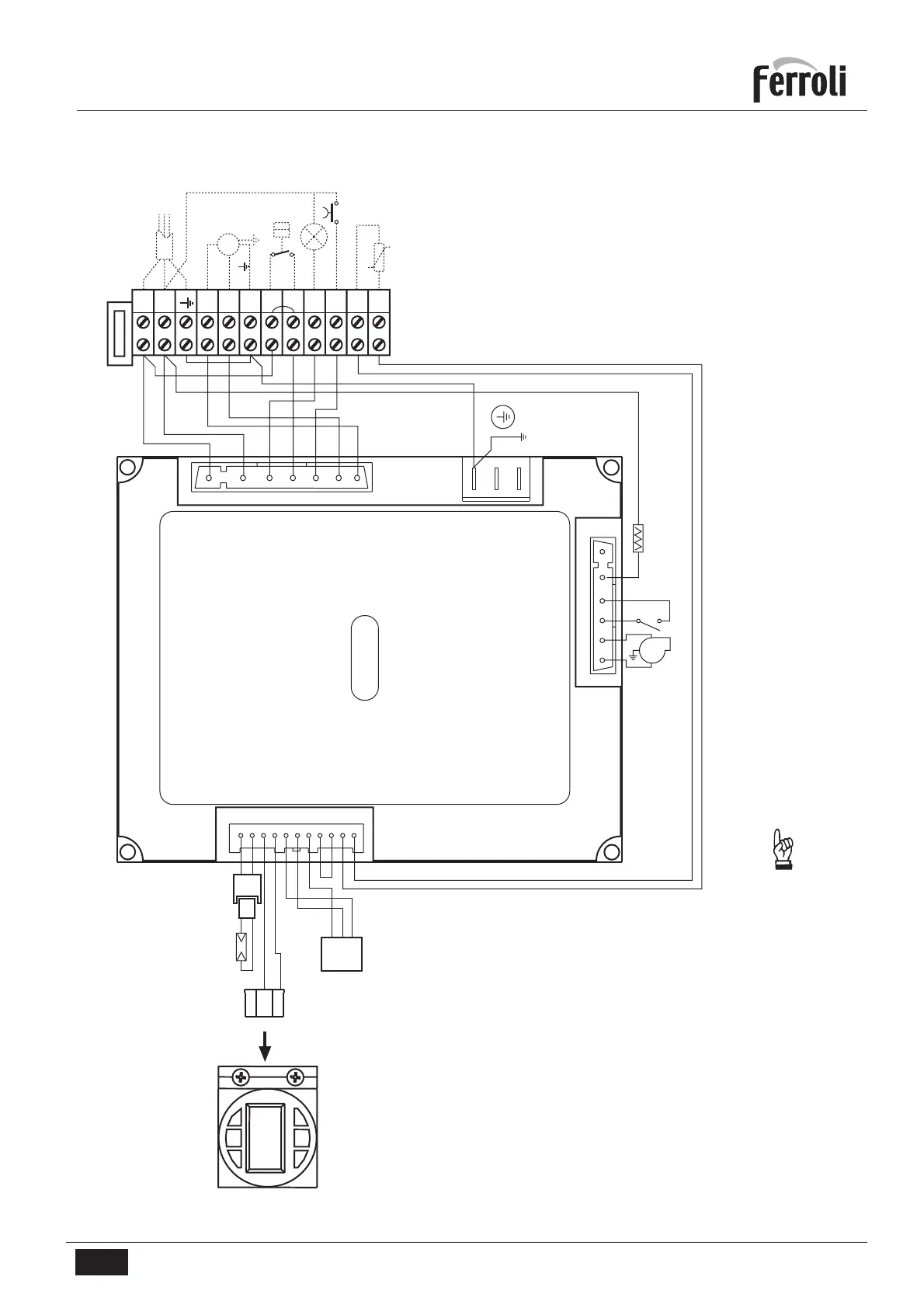
4.4 Wiring diagram
OUT
+15V
GND
DBM13
L
N
4
5
6
7
8
9
10
11
12
A
B
C
D
E
X2
X1
X3
218
239
16
297
FR
X7
INTERFACCIA
UTENTE BIT01.02
34
L
N
11
10
9
8
7
6
5
4
3
2
1
1
2
3
4
5
6
7
6 5 4 3 2 1
12
34
3.15 A
Key
FR Photoresistance
16 Fan
34 Heating temperature sensor
218 Pellet safety thermostat
239 Igniter
297 Air pressure transducer
A Electrical power supply
B Motor auger
C Request contact
D Shutdown signalling
E Burner reset
fig. 9
Important: Before connecting the request contact, remove
the jumper on the terminal block.
 Loading...