8 Technical data
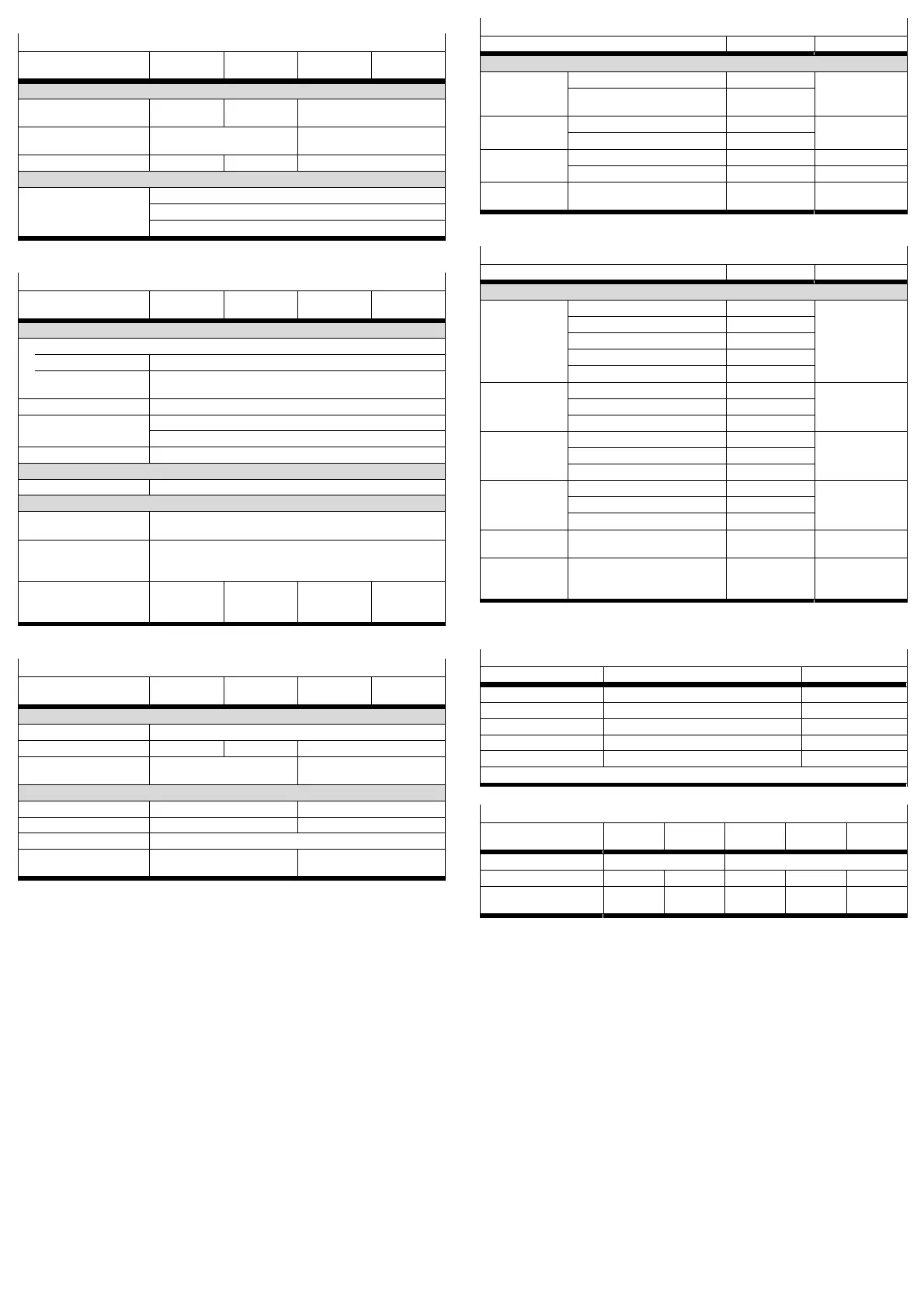
General
CMMP-AS- C2-3A-M3 C5-3A-M3 C5-11A-P3-M3,
C10-11A-P3-M3
C15-11A-P3-M3
Dimensions and weight
Dimensions
(HxWxD)
1)
[mm] 202x66x207 227x66x207 252x79x247
Mounting plate
dimensions
[mm] 248x61 297x75
Weight [kg] 2.1 2.2 3.5
Approvals
CE marking (see declaration
of conformity)
In accordance with EU Low Voltage Directive
In accordance with EU EMC Directive
In accordance with EU Machinery Directive
1) without plugs, screening screw and screw heads
Operating and environmental conditions
CMMP-AS- C2-3A-M3 C5-3A-M3 C5-11A-P3-M3
C10-11A-P3-M3
C15-11A-P3-M3
General
Permitted installation height above sea level
at rated output [m] 1000
with power
reduction
1)
[m] 1000 … 2000 (max.)
Air humidity [%] 0 … 90 (non-condensing)
Protection class IP20 (with plugged-in plug connectors at X6 and X9)
IP10 (without plugged-in plug connectors at X6 and X9)
Degree of contamination 2
Transport and storage
Temperature range [°C] -25 … +70
Operation
Operating temper
ature
[°C] 0 … +40
Operating temper
ature with power re
duction 2.5 % per K
[°C] +40 … +50
Shutdown temper
ature of power unit
heat sink
°C 100 80 80 85
1) Above 1000 m above sea level Performance reduction of 1% per 100 m
Power supply [X9]
CMMP-AS- C2-3A-M3 C5-3A-M3 C5-11A-P3-M3
C10-11A-P3-M3
C15-11A-P3-M3
Logic supply
Nominal voltage [V DC] 24 ±20 %
Nominal current
1)
[A] 0.55 0.65 1
Maximum current
for holding brake
2)
[A] 1 2
Load supply
Number of phases 1 3
Voltage range [V AC] 100 … 230 ±10 % 230 … 480 ±10 %
Mains frequency [Hz] 50 … 60
Alternative DC
supply
[V DC] 60 … 380 60 … 700
1) plus current consumption of a holding brake and I/Os, if present
2) for higher power requirements è Hardware description
I/O interface [X1]
Type Values Remark
Digital inputs/outputs
Inputs
DIN0 … DIN9
Input voltage [V] 24 active high, con
forms to
EN 61131-2
Voltage range [V] 8 … 30
Outputs
DOUT 0 … DOUT3
Output voltage [V] 24 active high, gal
vanically isolated
Voltage range
1)
[V] 8 … 30
+24 V Output voltage [V] 24
Max. output current [mA] 100
GND24 Voltage [V] 0 Reference poten
tial for digital I/Os
1) When used as a digital input (configuration with FCT)
I/O interface [X1]
Type Values Remark
Analogue inputs/outputs
AIN0
#AINO
Entry area [V] ±10 differential –
Resolution Bit 16
Time delay [μs] 250
max. input voltage [V] 30
R
I
[kΩ] 30
AIN1
1)
Entry area [V] ±10 Single-ended –
Resolution Bit 10
Time delay [μs] 250
AIN2
1)
Entry area [V] ±10 Single-ended –
Resolution [bit] 10
Time delay [μs] 250
AMON0, AMON1 Output range [V] ±10 –
Resolution [bit] 9
Critical frequency [kHz] 1
OGND Voltage [V] 0 Reference
potential
+VREF Output range [V] 0 … 10 Reference output
for setpoint
potentiometer
1) This input can also be optionally parameterised as a digital input with an 8 V switching
threshold (parametrisation with FCT).
Supported encoders [X2A]/[X2B]
Encoder type Protocol Interface
Resolver – [X2A]
Digital encoder Incremental [X2B]
Analogue encoder – [X2B]
EnDat encoder EnDat 2.1 (01/21); EnDat 2.2 (22) [X2B]
HIPERFACE encoder HIPERFACE [X2B]
Details è Hardware description
Motor connection [X6]
CMMP-AS- C2-3A-M3
1)
C5-3A-M3
1)
C5-11A-P3-
M3
2)
C10-11A-P3-
M3
2)
C15-11A-P3
-M3
2)
Voltage [VAC] 0 … 270 0 … 360
Rated output [kVA] 0.5 1 3 6 9
Max. power for 5
seconds
[kVA] 1 2 6 12 18
1) Data for operation at 1x230 VAC [±10 %], 50 … 60 Hz
2) Data for operation at 3x400 VAC [±10 %], 50 Hz
è All available technical data è Hardware description.
 Loading...


