Next to the sensor connections there is/are one or two
green LEDs. These indicate the state of the signal at
the relevant input. The meanings are as follows:
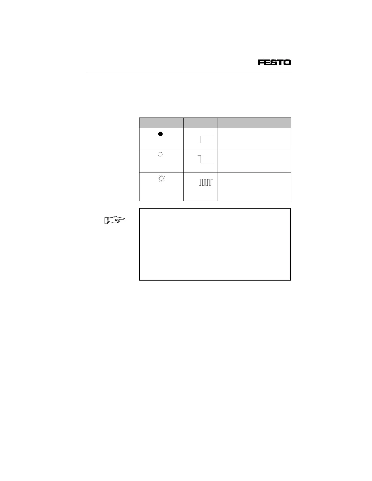
Status display
Status LED Sequence Status
LED lights up
1-signal
LED is out
0-signal
LED flashes
Only during switch-on phase:
- if there is a 1-signal and
- if there is a line assignment
error.
PLEASE NOTE
In conjunction with the CP field bus node:
If there is a line assignment error during the switch-
on phase, the CP node will switch the power supply
to the input module and also the power supply to the
connected sensors on and off cyclically. In this case,
the status LEDs and the LEDs of the connected
sensors will therefore flash, providing they transmit a
1-signal.
ON
OFF
ON
OFF
ON
OFF
1. Input module type CP-E16...-M...-...
CP-E16...-M... 9901b 1-25