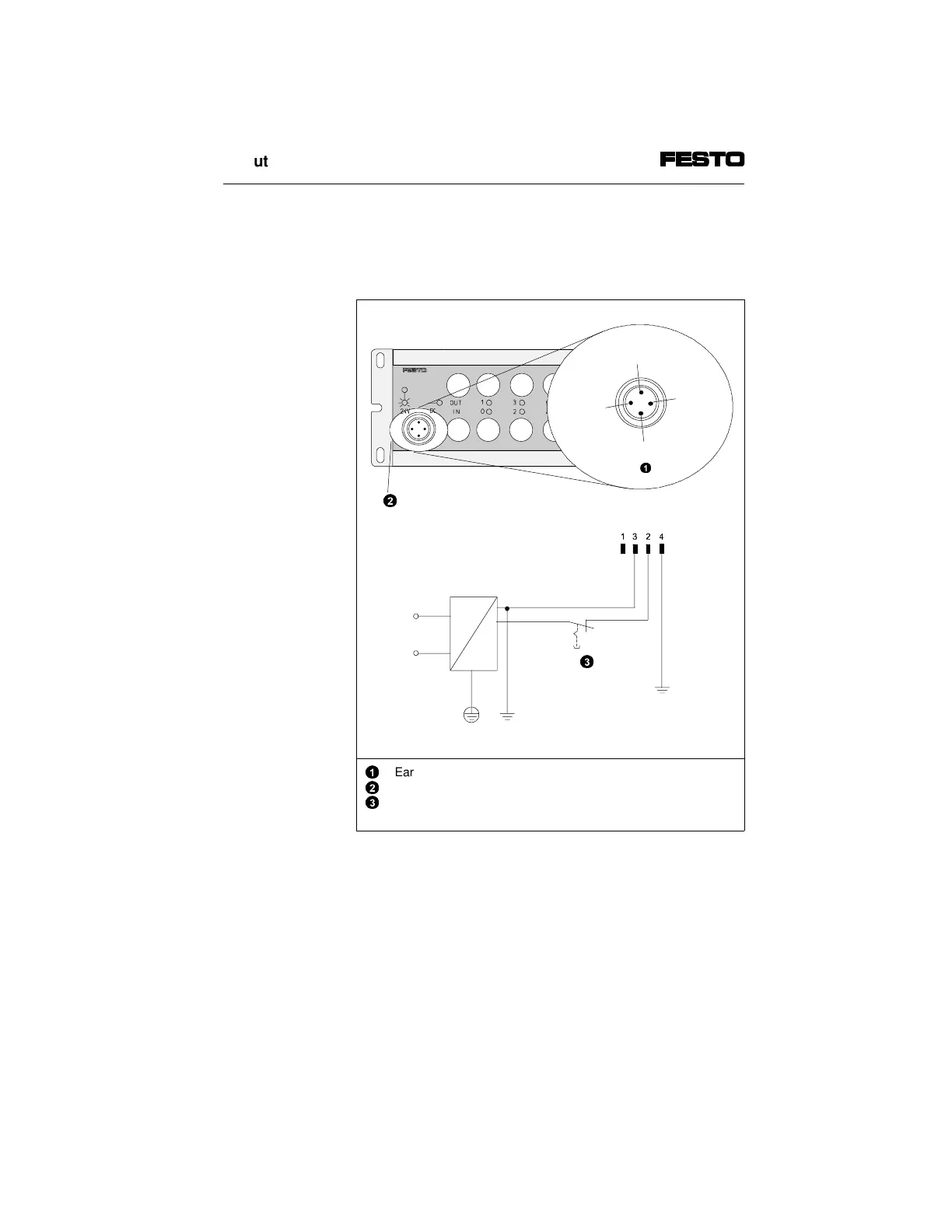
The diagram below shows the pin assignment of the
load voltage connection on the output module as well
as a connection example.
n.c.= not connected
1
2
3
Earth connection pin 4
Earth connection on side of housing
Load voltage can be switched off separately; the operating
voltage is supplied via the CP connection
Fig. 2/10: Pin assignment of load voltage connection
DIAG
POW ER
OUTPUT-P
Pin 1:
n.c.
Pin 4:
1
Pin 3:
0 V
Pin 2:
24 V DC ± 25%
2
3
2. Output module type CP-A08...-M12-...
CP-A08...-M12 9901b 2-15
 Loading...