Festo SPC11 2018-12b English8
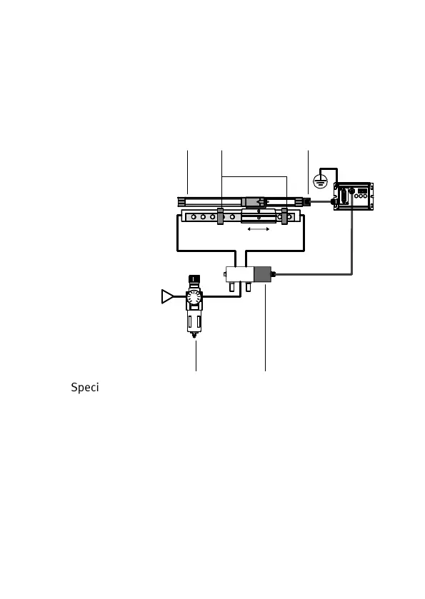
3.1 Overview of fitting and pneumatic installation
(example DGPL-... and MLO-POT-...-TLF)
1 Measuring system
2 Fixed stops
3 Measuring system
connection
4 Proportional
directional control
valve
5 Service unit
(without lubricator,
with 5 μm filter)
45
P.01P.02
1
24
Special instructions on the components used can be found
in the manuals for the SPC11.
Connections to the proportional directional control valve
When compressed air is applied to work connection 4,
movement is made in the direction of the zero point of the
measuring system. When compressed air is applied to
work connection 2, movement is made in the opposite
direction. With linear drives: the zero point of the measur
ing system lies on the side of the measuring system con
nection.
 Loading...