Festo SPC11 2018-12b English 9
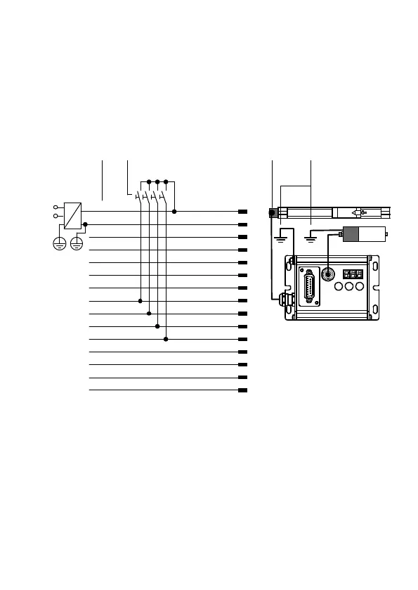
4 Fitting the electric components
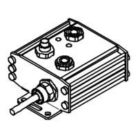
Example of fitting electric drive type DGP(L)-... and
measuring system type MLO-POT-...-TLF. Use only the
original cables specified.
24 V
0 V
O1: P.01
O2: P.02
O3: P.03
O4: P.04
*)
O5: Error
*)
I1: P.01
I2: P.02
I3: P.03
I4: P.04
*)
I5: +/}
I6: Enter/Teach/Esc
I7: {/–
I8: Remote
15
14
13
12
11
10
9
8
7
6
5
4
3
2
1
white-yellow
brown-green
white-green
red-blue
grey-pink
violet
black
red
blue
pink
grey
yellow
green
brown
white
12 3 4
*) The function of this input/output can be configured
(see system manual P.BE-SPC11-SYS-...)
1 Pin assignment for Control
connection with core colours
for cable KMPV-SUB-D-15-...
O..: output, I..: Input
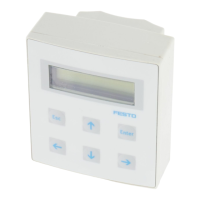
2 Button for moving to the
positions
3 With linear drives, end
position 1 lies on the side
with the electrical
connections to the
measuring system.
4 Earth/ground
 Loading...