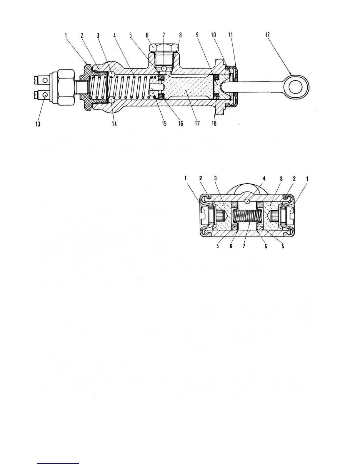
FIG 10:7 Master cylinder section
Key to Fig 10:7 1 Plug and spring seat 2 Body 3 Front wheel brake line duct 4 Plunger return spring
5 Compensating hole 6 Plug 7 Supply duct 8 Fluid inlet hole 9 Plunger 10 Plunger snap ring 11 Boot
12 Pushrod 13 Terminal, stoplight switch 14 Rear wheel brake line duct 15 Holes in floating ring carrier for fluid passage
16 Valve 17 Valve carrier 18 Seal
FIG 10:8 Wheel cylinder section
Key to Fig 10:8 1 Shoe actuating stems 2 Boot
3 Plungers 4 Fluid inlet hole 5 Seal rings
6 and 7 Spring thrust cups and plunger reaction spring
Apply the brakes hard for several minutes and inspect the
master cylinder and hydraulic connections for leaks.
10:6 Wheel cylinder operation
Hydraulic pressure from the master cylinder reaches
the fluid in the wheel cylinders by hydraulic pipes and it
forces the plungers 3 (see FIG 10:8) apart and through
the plungers the brake shoes operate. In the wheel
cylinders the sealing rings 5 are axially compressed by
the cup 6 under the action of the spring 7. The rings are
under the radial and axial action of hydraulic pressure
so that their sealing efficiency is increased as the
hydraulic pressure increases.
Checking wheel cylinders:
Once the wheel cylinders have been removed from
the brake backplate as previously described remove the
rubber boots 2 (see FIG 10:8) on the ends of the cylinder.
The plungers, brake shoe stems and sealing rings will be
pushed out due to normal spring expansion. Remove the
spring thrust cups and plunger reaction spring.
107
F500
Master cylinder reassembly:
Ensure that the metal parts are clean. Dry off any
solvent used for cleaning. Renew all the rubber seals as
a matter of course. Wet the internal parts with clean brake
fluid and reassemble them in the order shown in FIG
10:7.
Refitting the master cylinder:
Carefully locate the master cylinder flange to the body
panel ensuring that the pushrod 12 (see FIG 10:7)
correctly locates in the plunger 9. Secure the master
cylinder flange using the two nuts and spring washers.
Refit the hydraulic pipes.
Remove the tapered wooden plug from the reservoir
and bleed the system as described in Section 10:10.
Dismantling master cylinder:
1 Refer to FIG 10 :7 and remove the plunger and rubber
boot from the cylinder body.
2 Using a pair of circlip pliers remove the plunger
circlip.
3 Carefully slide off from the inside of the cylinder body
the plunger, plunger seal, valve ring carrier, valve ring
and the reaction spring.
4 Remove the stoplight pressure operated switch.
5 Remove the cylinder body stop plug and upper plug.
6 Carefully inspect the master cylinder inner surface and
plunger outer surface to ensure that they have a mirror-
like finish and that the play between the two parts is
not excessive. Any roughness present on the cylinder
inner surface will necessitate renewing the complete
assembly. Scoring or corrosion of the surface will
quickly damage the rubber seals and can lead to
leakage of fluid and consequent partial or complete
brake failure. Check that the plunger return spring is not
corroded or distorted.