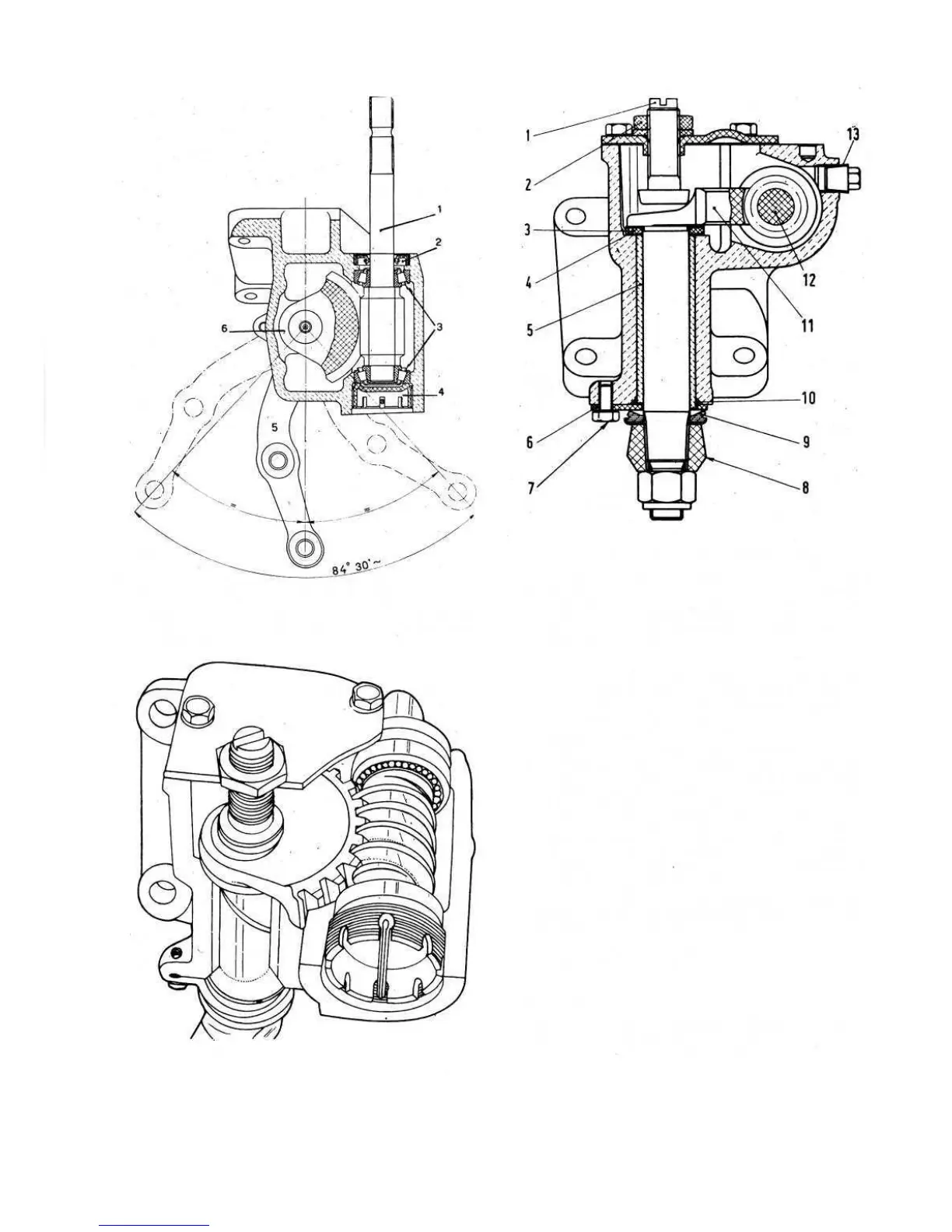
FIG 9:4 Section of steering box, through worm screw
Key to Fig 9:4 1 Worm screw 2 Seal 3 Roller bearing
4 Worm screw adjuster and bearing retainer 5 Pitman arm
6 Worm sector
FIG 9:6 Steering box cutaway
100
FIG 9:5 Section of steering box, through worm sector
Key to Fig 9:5 1 Sector adjustment screw 2 Locking
nut and plain washer 3 Sector thrust washer 4 Shim
5 Eccentric bush 6 Bush adjusting plate 7 Plate screw
and toothed washer 8 Pitman arm 9 Sector lower seal
10 Upper seal 11 Worm sector 12 Worm screw
13 Oil filler and level plug
2 If play is excessive in the worm screw rollers, screw up
the lower adjuster ring 4 (see FIG 9:4). Once adjust-
ment has been completed the adjuster ring must be
secured by the cotter. The ring should be positioned
so that the hole in the steering box lines up with one
of the spaces between the ring castellations.
3 Should the meshing between the worm screw and the
sector not be at the correct central position this
condition may be rectified by moving the sector
axially. To do this add or remove shims (see FIG 9 :5)
below the thrust ring of the worm sector. The final
adjustment must be carried out by using the adjust-
ment screw 1 (see FIG 9:5) on the cover and then
locking the screw by nuts 2. In service shims are
supplied .0039 inch thick.
The above described adjustments must eliminate
any play and back lash in the steering gear without
rendering the steering gear stiff to operate between
the two locks.
4 During adjustment should any seal be found to be
damaged then it should be renewed.
Reassembly:
Reassembly is the reverse procedure to dismantling
but the following points should be noted:
1 All parts should be thoroughly cleaned before