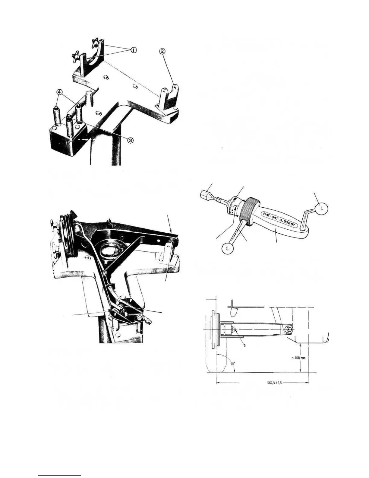
FIG 7:3 Fixture A.66064, for swinging arm inspection
and adjustment
Key to Fig 7:3 1 Clamp screws, securing wheel shaft on
fixture 2 Alignment bracket, swinging arm member check-up
3 Nut, to secure swinging arm external support on fixture stud
4 Swinging arm external support centring pins
A
B
C
D
FIG 7:4 Adjusting right rear suspension swinging arm
on fixture A.66064
Key to Fig 7:4 A and B Swinging arm external support
adjustment shims C and D Swinging arm internal support
adjustment shims
torque wrench setting of 43.4 Ib/ft.
3 During assembly the bearings must be packed with
Fiat MR grease, taking care not to overpack as this
can result in early bearing failure.
82
4 If the axle shaft to flexible joint tie sleeve has been
removed, the mating splines must be coated with Fiat
B2G grease on re-installation.
5 Preload the wheel bearings and adjust the swinging
arm as described later on in this section.
Wheel bearing adjustment:
To ensure a long bearing life due to correct initial
adjustment the ballbearings should be preloaded and to
do this proceed as follows:
1 Tighten the wheel shaft nut gradually so that the
rotation torque does not exceed .36 Ib/ft.
2 To check the rotation torque install Fiat tool A.95697/2
on the wheel drum and insert the shank 2 (see FIG
7:5) of dynomometer A.95697 in the support and
securely hold the lever 3. Move the needle 5 to register
.36 Ib/ft on the dynomometer scale as shown in FIG
7:5 and using the operating lever 6 rotate the dyno-
mometer and the wheel shaft some turns in a clockwise
direction. During rotation check that the needle 5 does
not exceed the setting index 4. Should the rotation
torque prove to exceed .36 Ib/ft, this will indicate a
4
3
1
6
5
2
FIG 7:5 Bearing rotation torque dynamometer
KeytoFig7:5 1 Dynamometer A.95697 2 Dynamometer
shank to insert in item A.95697/2, fitted to wheel drum
3 Dynamometer grip lever 4 Rotation torque setting index
5 Adjustable needle 6 Dynamometer operating lever
Oil Sump
Wheel Plane
HALF TRACK
FIG 7:6 Position of rear suspension and of vehicle for
rear wheel toe-in inspection and adjustment
Key to Fig 7:6 ~ 168 mm = 6.61 inch
567,5 ± 1,5= 22.342 inch ± .059 inch