2 Using Fiat puller A.46023 as shown in FIG 8:9
remove the wheel grease cap.
3 Using a universal two leg puller or Fiat puller A.40005
together with items 1 and 9 remove the wheel hub/
drum assembly having first extracted the splitpin if
fitted and released the hub retaining nut (see FIG
8:10).
Dismantling brake unit:
1 Using a compressed air jet thoroughly clean all com-
ponents of the brake assembly.
2 Make a note of the location of the shoe return springs
and gently ease the shoes away from the brake
backplate (see FIG 10:2).
3 Disconnect the hydraulic line from the rear of the
wheel cylinder and remove the two cylinder retaining
bolts. Lift away the hydraulic cylinder.
Brake shoe lining:
Check the lining thickness and if found to be exces-
sively reduced service replacement shoes must be fitted.
The minimum allowable brake lining thickness is .059
inch.
Thoroughly check the linings for signs of oil or grease
which, if evident, the shoes must be renewed and the
drums and oil seals thoroughly inspected for the cause
of oil ingress and the cause remedied before reassembly.
Do not fit odd brake shoes and do not mix materials or
unbalanced braking will result.
Do not allow grease, oil or paint to contact the friction
linings.
Brake drums:
Whilst servicing the brakes, thoroughly inspect the
drums for scoring, ovality or distortion as well as inspect-
ing for minute hair line cracks. The drums may be refaced
by using a centre lathe and finally finishing by lapping
the drums to smooth out possible tool marks. The
maximum permissible oversize beyond the nominal drum
diameter of 6.702 to 6.712 inch is .039 inch. This limit
must never be exceeded otherwise the strength of the
drum will be impaired or a reduction in braking efficiency
caused by the increase of shoe expansion travel and the
consequent diminished contact pressure.
No brake adjustment will be required on the new 500
Saloon models after the drum has been reassembled as
the self-adjusting device will accommodate for the shoe
position to the new drum diameter during the first
operation of the brake pedal.
Reassembly of front brakes:
This is the reverse procedure to dismantling. Ensure
that the pull-off springs are correctly fitted to the holes in
the webs of the brake shoes and that the shoes register
correctly in the slotted ends of the pistons and the
side
mounting plate.
Upon assembly of the hub and brake drum assembly
liberally pack the space between the two bearings with
Fiat MR grease, and remount the hub according to the
instructions in Chapter 8.
F500
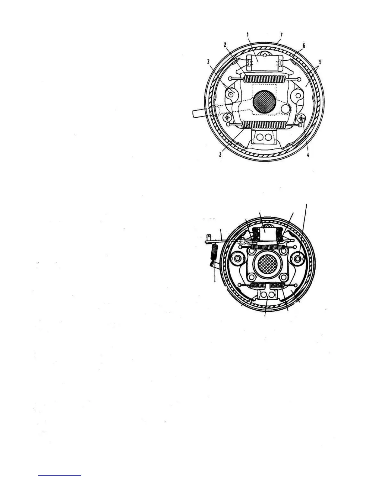
FIG 10:3 Section view of left side front brake assembly
(500 Station Wagon)
Key to Fig 10:3 1 Wheel cylinder 2 Shoe return spring
3 Adjusting cams 4 Shoe guide pin 5 Shoe with lining
6 Drum 7 Housing flange
BRAKE SHOE
ADJUSTING DEVICE
SHOE WEDGE
SELF
WHEEL CYLINDER
SHOE RETURN SPRING
PARKING BRAKE
SHOE CONTROL
RETURN SPRINGS
LEVER
SHOE LOCK PLATE
BRAKE SHOES
SHOE RETURN SPRING
SHOE MOUNTING PLATE
FIG 10:4 Right rear wheel brake assembly (500 Sedan)
10:4 Rear brakes
Rear brake drum removal:
1 Remove the wheel trims and carefully slacken the road
wheel retaining bolts. Using a garage hydraulic jack
raise the rear of the vehicle and place on firmly based
stands. Remove the road wheels.
2 Remove the four drum to hub retaining bolts and
spring washers and carefully withdraw the drum from
the backplate assembly.
Dismantling brake unit:
1 Using a compressed air jet thoroughly clean all
components of the brake assembly.
105