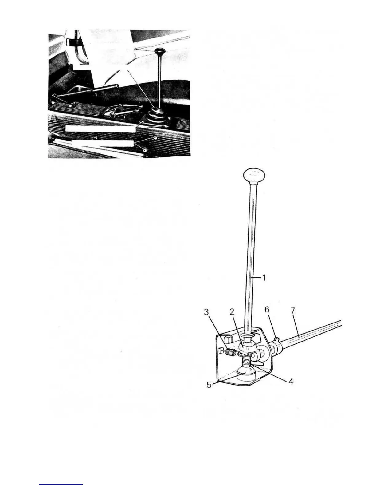
LEVER SUPPORT SCREWS
BOOT MOUNTING SCREWS
GEARSHIFT LEVER BOOT
GEARSHIFT LEVER
FIG 6:17 Location of gearshift lever on control passage
tunnel
Repair and inspection :
Whilst servicing the assembly thoroughly check the
condition of the slip joints sliding surfaces and the
housing in the differential side gears. If, due to wear, the
clearance is greater than .008 inch the slip joints should
be renewed or in extreme cases the differential side gears
as well.
Also check the clearance between the slip joint pivots
and runners and if it is found to be excessive the axle
shafts must be renewed as well as the runners as the
joint pivot is not supplied as a service spare part. The axle
shaft to sliding sleeve spline clearance should not exceed
.006 inch.
Check that the sliding sleeve snap ring is a snug fit in
its seating groove on the shaft.
Whenever the vehicle is being serviced the condition
of the boots, bushings and oil seals should be checked
and any damaged parts renewed.
6:10 Gear shift control mechanism
Should difficulty be experienced in obtaining correct
gear selection then the gear shift control mechanism
should be adjusted as follows:
1 Remove the screws fixing the cover to the tunnel and
raise the cover to the top of the gear shift lever stem.
2 Slacken the lever support mounting screws and push
the support forward if first- and third-speed engage-
ment is incorrect or backwards if second-, fourth- and
reverse-speed engagement are incorrect. Finally tighten
the mounting screws. Refit the gear shift lever boot.
Removal:
To remove the gear shift control mechanism from the
car proceed as follows:
1 Unscrew the gear shift control lever knob and the boot
fixing screws and slide the boot from the gear shift
lever.
76
Key to Fig 6:18 1 Hand lever 2 Inner lever
3 Lever return spring 4 Hand lever spring 5 Ball seat
6 Inner lever-to-rod mounting screw 7 Gearshift control rod
FIG 6:18 Gearshift control mechanism
6:11 Modifications
Various design modifications are incorporated on the
500 sedan (110F) and the late version of the 500 station
wagon. These are shown in FIGS 6:19 and 6:20,
The gear shift handlever is removed by releasing the
lever to support mounting self-locking nut.
Check that the lever ball and socket are in good
condition and not badly pitted or worn. The inner lever
return spring and the hand lever spring should be checked
for weakness which, if apparent, should be renewed.
Reassembly is the reverse procedure to dismantling.
Dismantling and inspection:
2 Remove the screws fixing the assembly to the tunnel.
Remove the tunnel front cover.
3 Disconnect the gear shift control rod at the gear
engagement control lever and pull out the assembly
from the front end.



 To Next Page