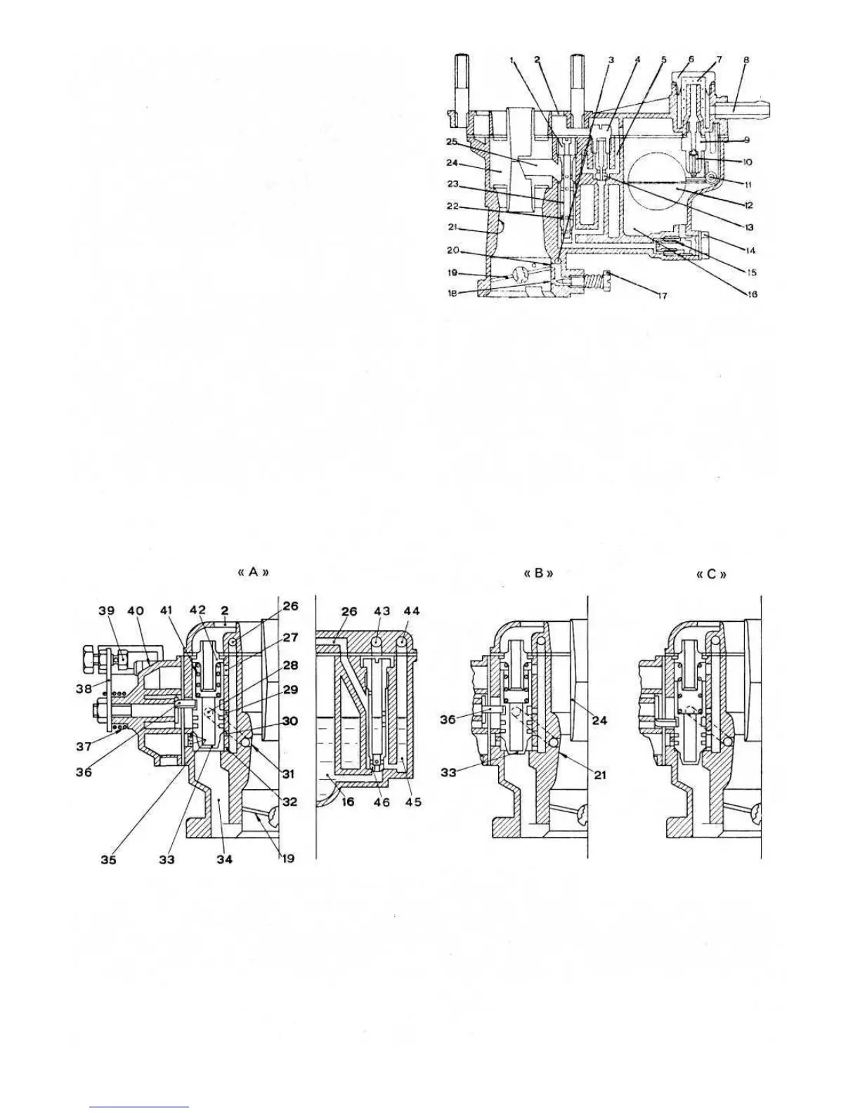
FIG 2:5 Starting device (choke) diagrammatic section
KeytoFig2:5 A Device fully inserted B Device partially inserted C Device disinserted 2 Air inlet 16 Bowl
19 Throttle 21 Primary venturi 24 Secondary venturi 26 Mixture duct 27 Mixture leaning air orifice
28 Transition duct 29 Transition mixture orifice 30 Starting mixture orifice 31 Transition orifice
32 Starting mixture orifice 33 Starting valve 34 Mixture duct 35 Starting device air orifices 36 Rocker
37 Lever return spring 38 Starting device control lever 39 Control wire screw 40 Cover with support for starting
device control bowden 41 Starting valve spring 42 Spring casing. 43 Starting jet emulsion air orifice
44 Air emulsion reserve well orifice 45 Starting reserve well 46 Starting jet
F500
37
FIG 2:4 Diagrammatic section of Weber 26.IMB
carburetter
KeytoFig2:4 1 Air corrector jet 2 Air inlet
3 Idle speed mixture duct 4 Idle speed jet holder
5 Idle speed air orifice 6 Filter cover 7 Filter
8 Fuel inlet connection 9 Needle valve seat 10 Needle
11 Float pivot 12 Float 13 Idle speed jet
14 Main jet holder 15 Main jet 16 Bowl
17 Idle speed mixture adjustment screw 18 Idle speed
mixture orifice 19 Throttle 20 Transition hole
21 Primary venturi (not interchangeable) 22 Emulsion
orifices 23 Emulsion well 24 Secondary venturi
(not interchangeable) 25 Main nozzle
design with a 1.0236 inch diameter throat measured at the
height of the throttle shaft. The amount of charge passing
to the manifold is controlled by a throttle butterfly valve
from an accelerator pedal operating a lever secured to the
throttle valve shaft via a cable. The carburetter is fitted with
a progressive action starting device which enables the
driver to suit the mixture richness to the most arduous of
starting conditions, and will enable the engine to run
evenly until it reaches its normal operating temperature.
A dampened needle valve ensures a smooth running
engine as it is not affected by engine vibrations and there-
fore giving a constant fuel level in the carburetter bowl. A
secondary venturi is incorporated in the single casting of
the carburetter body and this has a diameter of 0.8268 inch.
Carburetter operation:
Filtered air flows through the venturi 24 (see FIG 2 :4)
where it mixes with fuel flowing from the nozzle 25 and
the charge is then conveyed to the cylinders through the
primary venturi 21 and throat, where the throttle butterfly
19 controls the amount of charge.
Petrol flows from the main fuel line to the bowl 16
through a gauze filter 7 and needle valve 10, where the
float 12 pivoting at point 11, controls the opening of the
needle 10 so maintaining a constant fuel level. From the
bowl 16 fuel reaches the emulsion well 23 via the metered
main jet 15 where, after having been mixed with the air
coming from the metered air corrector screw 1, through
the emulsion orifices 22 and spray nozzle 25, it finally
reaches the Venturis where it mixes with the air stream