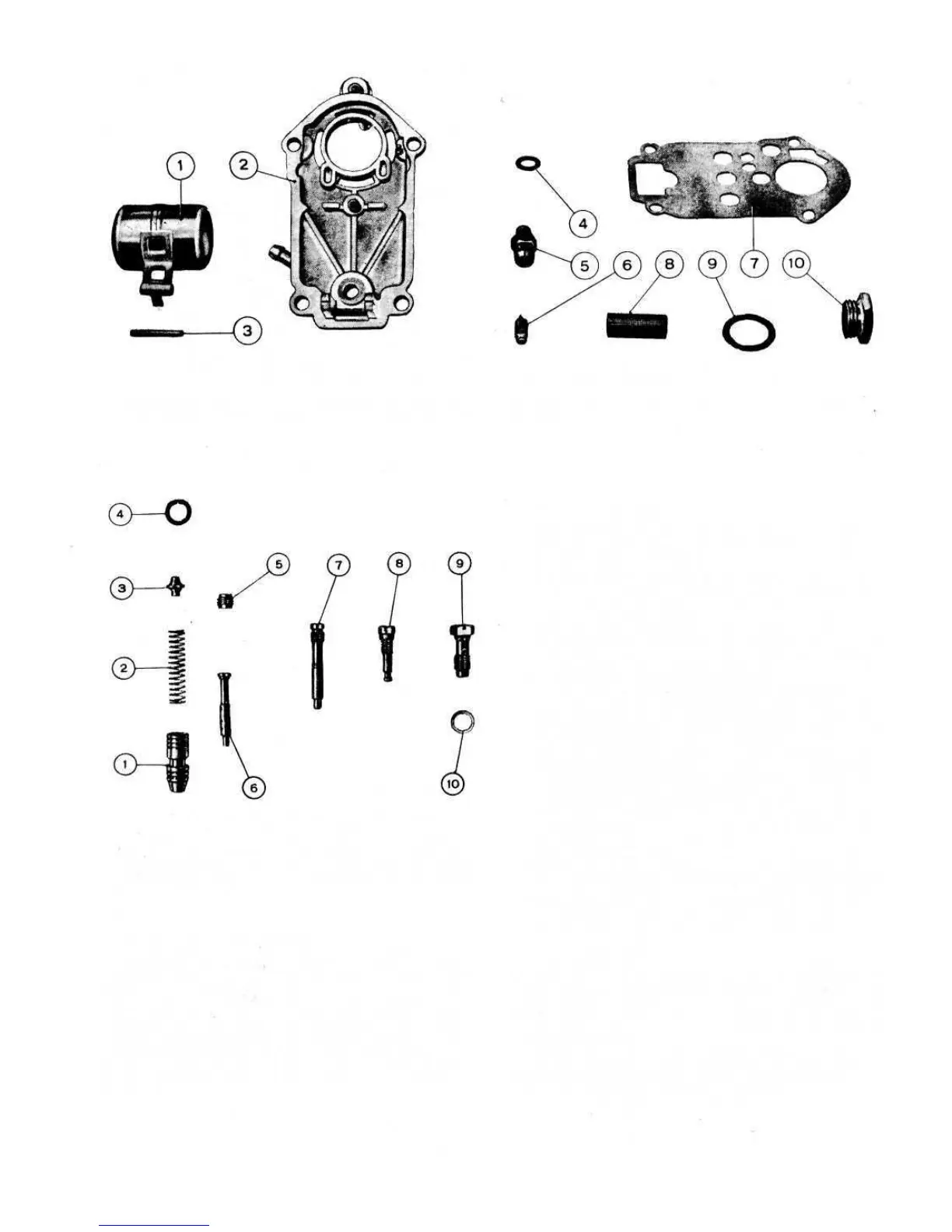
FIG 2:9 Weber 26.IMB carburetter cover components
Key toFig 2:9 1 Float 2 Carburetter cover 3 Float pivot 4 Needle valve gasket 5,6 Needle valve seat and needle valve
7 Cover gasket 8 Filter strainer 9 Gasket 10 Filter inspection plug
Carburetter cleaning:
To thoroughly clean the carburetter proceed as follows:
1 Passages. All fuel passages have a diameter that is
specially calibrated to ensure best operating conditions.
It is therefore essential that any dirt or scale that has
been deposited by petrol must be removed. Thoroughly
clean with petrol and blow dry using a compressed air
jet directed through all the passages in the castings. It is
essential that no drills or other metal objects be passed
through the jets or the passages otherwise these could
alter the finely calibrated diameters.
2 Calibrated parts. Idling and main jet holders, and the
relevant bayonet coupled jets are easily removed by
using a suitably sized wrench or screwdriver. To clean
the different calibrated parts, thoroughly wash in petrol
and blow dry using a compressed air jet. Do not use any
fine drills or metallic points as these may alter the fine
calibration of the orifices. Should it be necessary to dis-
mantle the carburetter adjustment components for
inspection always ensure that after reassembly of the
parts that they are seated correctly to avoid possible
operating troubles in the future.
3 Filter. To clean the filter unscrew and remove its plug
10 (see FIG 2 :9) located on the top of the carburetter
cover and then gently ease out the filter. Wash the filter
carefully in petrol, also ensure that the filter seat is clean
and then blow dry using a compressed air jet.
2:7 Modifications
The Weber 26.IM B carburetter has undergone a number
of minor changes during the development of the Fiat 500
models, but no changes in servicing procedure are made
necessary. Jet sizes and other calibrations are detailed
in Technical Data.
From 1970, the mounting flange of the carburetter is
slightly modified to incorporate a different mixture
adjustment screw, as shown in FIG 2:11.
40
Throttle valve components:
The throttle valve shaft should rotate freely in its guides
and this should be checked when the engine is at its
normal operating temperature. Any excessive clearance
caused by wear or the throttle valve butterfly distorted are
liable to cause irregular engine operation which will be
more pronounced at idling speed. Should the above con-
ditions be evident then the throttle valve butterfly and the
shaft assembly together with its sealing rings must be
renewed.
FIG 2:10 Jets, jet holders and choke valve
Key to Fig 2:10 1 Choke valve 2 Spring
3 Spring retainer and guide 4 Lock ring 5 Air bleed jet
6 Emulsion well 7 Choke jet 8 Idling jet holder and jet
9 Main jet holder and jet 10 Main jet holder gasket