3 Engine warm-up:
As the engine begins to warm up to its normal operating
temperature, gradually push home the starting device
lever so as only to supply the engine with the richened
charge enabling the cold engine operation to be smooth
and regular. Position 'B' (FIG 2:6).
4 Normal car driving:
Once the engine has reached its normal operating
temperature the starting device should be completely
brought out of operation by bringing the control lever to
the position 'C (FIG 2:6).
Idle speed adjustment:
The idling speed of the engine is adjusted by means of a
throttle setscrew and the mixture setscrew, the position of
which are shown in FIG 2:7. The throttle screw allows for
the adjustment of the throttle butterfly opening, the coni-
cal mixture setscrew meters the amount of charge issuing
from the idling speed passage which causes the mixture
to blend with the air flowing past the throttle that leaves a
gap between its edges and the throat walls. This ensures
a correct petrol/air mixture ratio best suited to the engine
requirements giving smooth operation.
The engine idling speed must always be adjusted when
the engine is at its normal operating temperature and then
setting the throttle butterfly position to its minimum open-
ing position by adjusting the throttle setscrew so giving a
steady engine speed. Turn the mixture screw in or out so
as to set the mixture richness to the most suitable ratio for
the selected throttle opening. This will accomplish a fast
but steady idling. Reduce the minimum throttle opening
slightly by adjusting the throttle setscrew until the best
idling speed is obtained.
Adjustment of fuel level in float chamber:
The needle valve, seating and float are easily accessible
for inspection by removing the carburetter top cover. Before
checking the petrol level in the float chamber, ensure that
the needle valve seat is screwed well home and that the
gasket is in place. Also check that the calibrated orifice in
the valve seat is unobstructed and not worn and finally
check that the needle slides freely in its guide. Should the
valve and seating be leaking, then the valve assembly must
be renewed. Check that the float is not distorted or punc-
tured and that it moves on its pivot without resistance or
excessive play. Again renew the float assembly if there is
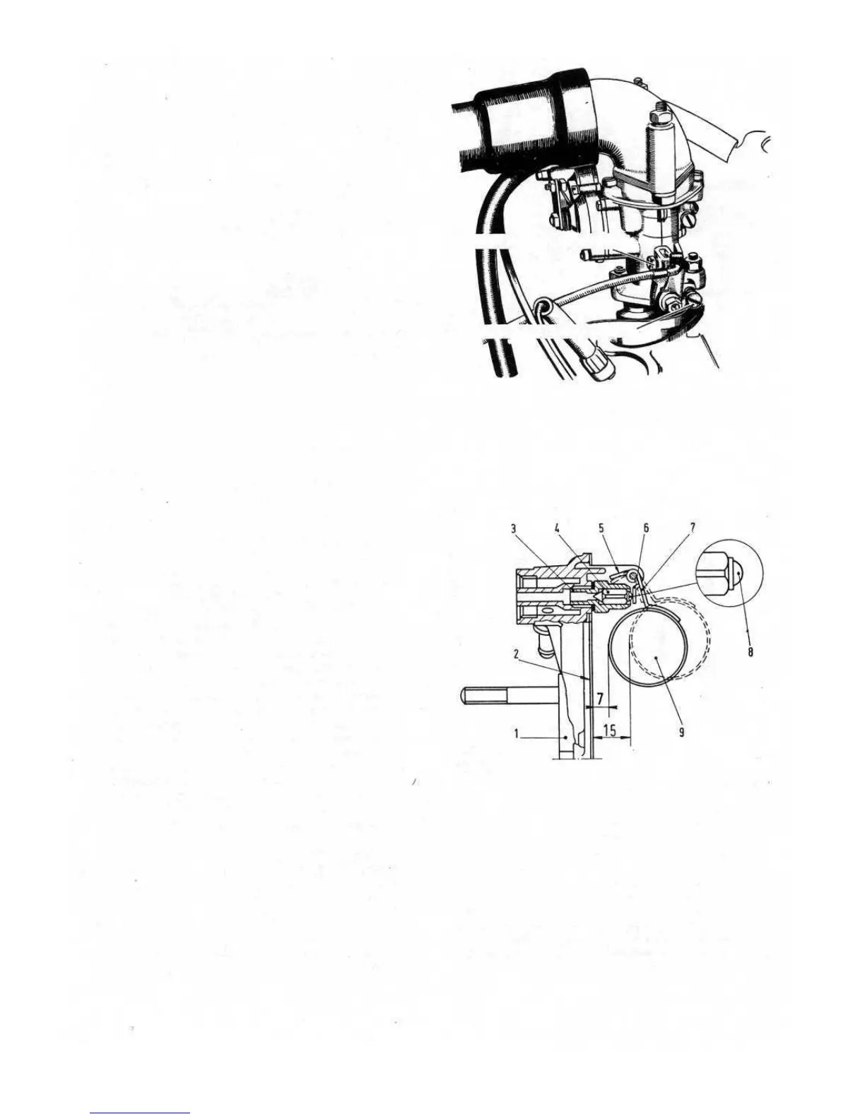
any doubt. To check the level proceed as follows:
1 Check that the needle valve 3 (see FIG 2 : 8) is screwed
tight on its seat.
2 Keep the carburetter cover 1 upright or else the weight
of the float 9 will lower the ball 8 fitted on the needle 4.
Check that with the cover held in the vertical position
and the float arm 6 in slight contact with the ball 8 of the
needle 4, the float is 5/16 inch away from the cover with
its gasket 2
fitted flat against the cover face.
3 Check that the float travel is 5/16 inch and if necessary
bend the lug 5 to give the required settings.
4 If the float 9 is not correctly positioned, bend the float
arms 7 until the correct adjustment is obtained. Ensure
that the arm 6 is perpendicular to the needle axis and
F500
39
does not show any rough spots or indentations which
might impair free movement of the needle. Check that
the float 9 freely moves about its pivot pin.
Every time a new float or needle valve assembly is fitted
the above detailed adjustment operations must be com-
pleted to ensure correct fuel levels.
FIG 2:8 Float adjustment data
Key to Fig 2: 8 1 Carburetter cover 2 Cover gasket
3 Needle valve seat 4 Needle 5 Lug 6, 7 Arms
8 Needle ball 9 Float 7 .2756 inch 15 .5906 inch
FIG 2:7 Weber 26.IMB carburetter in place on
engine. Idle speed is adjusted by working respectively
on throttle setting screw and mixture metering screw
THROTTLE SETTING SCREW
MIXTURE METERING SCREW