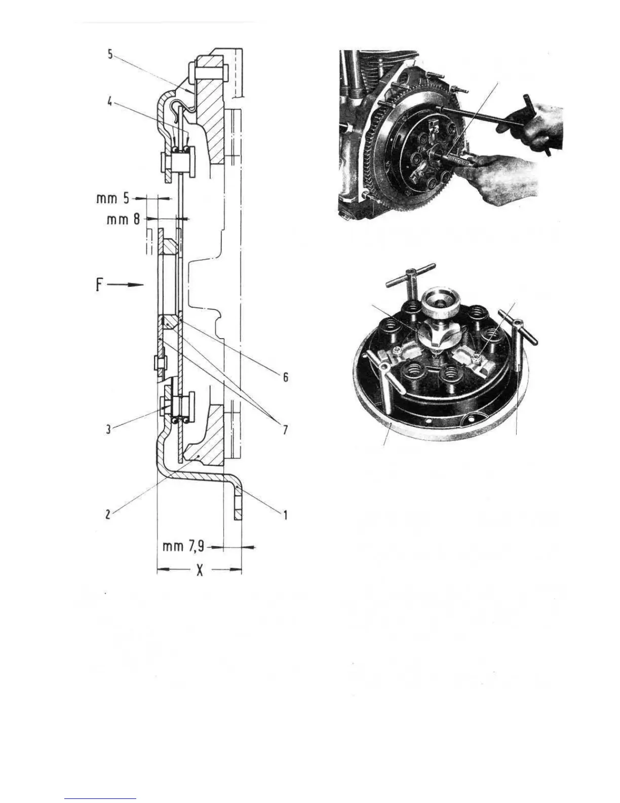
FIG 5.4 Clutch cover assembly inspection diagram
500F, L and later Station wagon
KeytoFig5:4 1 Clutch cover 2 Pressure plate
3 Clutch release flange plate 4 Diaphragm spring rings
5 Diaphragm spring retainer plate 6 Diaphragm spring
7 Clutch release flange
X =1.463 ± .043 inches
F = direction of clutch release flange movement
8 mm = .31 5 inch = release travel
5 mm = .197 inch = maximum allowance for driven plate lining
wear
7.9 mm = .311 inch
62
5:5 Installation of clutch on flywheel
Before assembling the clutch cover assembly and
driven plate the following parts of the unit should be
assembly proceed as follows:
1 Position the clutch cover assembly on Fiat fixture
A.62038 with a spacer .311 inch thick between the
cover and the plate.
2 Operate the clutch mechanism for four complete
throw-out strokes by applying a load of at least 181 Ib
on the release flange as shown by the arrow 'F' in
FIG 5:4.
3 Check that with a withdrawal travel of .315 inch the
pressure plate is displaced .071 inch. Also check that
the distance'X' (see FIG 5 :4) is 1.463 inch ± .043 inch.
Should the results obtained not compare with the
manufacturers recommended figures, then the clutch
cover assembly should be renewed.
FIG 5:6 Fixture A.62038 for clutch disassembly, re-
assembly and adjustment (new 500, 500D sedan and early
station wagon)
FIXTURE A. 62038
T-HANDLES
CARRIER RING
LEVER
BOLT NUTS
(LEVER ADJUSTMENT)
FIG 5:5 Installing the clutch on flywheel using pilot
A.62023 (new 500, 500D sedan and early station wagon) to
centre the driven plate
PILOT A. 62023 FOR
DRIVEN
PLATE CENTERING