2322
Fusion
Splicing Process
During fusion, the bers are joined together and subjected to ve dierent currents
as illustrated below. An important parameter, which changes during splicing, is
the distance between the bers. During Pre-fusion, the bers are apart. With the
current phase changing, bers are spliced gradually.
The most important splicing parameters are the time and current, each current
phase is shown below, that the name and function and other parameters are
important to the splice process are described under “Parameters for Normal
Splicing Process” on the next page.
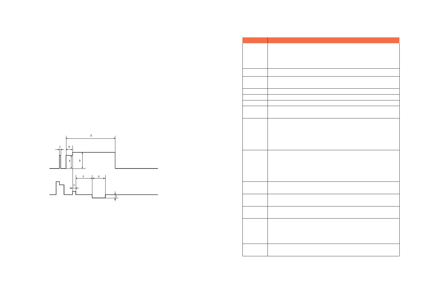
The following gure shows the discharge conditions (The relationship between the
“discharge intensity" and "motor move"). We can change the splicing parameters
listed below to change the discharge conditions.
A: Pre-fuse power B: Arc power C: Cleaning Arc
D: Pre-fuse time E: Arc time F: Overlap
G: Taper wait time H: Taper time related to taper length I: Taper speed
Diagram of ARC discharge condition
4.4 Parameters for Normal Splicing Process
Parameter Description
Template
A list of splice modes stored in the splicer database is displayed.
Upon inputting the appropriate mode, the selected splice mode
stored in database area is copied to a selected splice mode in user-
programmable area.
Name Title for a splice mode expressed in up to seven characters.
Note
Detailed explanation for a splice mode expressed in up to 15
characters. It is displayed at “Select splice mode” menu.
Focus-L Set the focus parameter for lens X.
Focus-R Set the focus parameter for lens Y.
Arc adjust Set to adjust arc power according to the bers’ conditions.
Pull test
If “Proof test” is set to “ON”, a pull-test is performed upon opening
the windproof cover or by pressing the SET button after splicing.
Loss
estimate
Loss estimate should be regarded as a reference. Since the loss is
calculated upon the ber image, there is certain dierence with the
real value. The estimate method is based on a single mode ber and
calculates at the wavelength of 1.31μm. The estimated value can be a
valuable reference, but cannot be used as the basis of acceptance.
Minimum
loss
This amount is added to the estimate splice loss originally calculated.
When splicing specially or dissimilar bers, a high actual splice loss
may occur even with optimized arc conditions. To make the actual
splice loss concur with the estimated splice loss, set the actual splice
loss to minimum value (minimum loss).
Loss Limit
An error message is displayed if the estimated splice loss exceeds
the selected threshold (loss limit).
Core angle
limit
An error message is displayed if the bend angle of the two bers
spliced exceeds the selected threshold (Core angle limit).
Cleave angle
limit
An error message is displayed if the cleave angle of either the left or
right ber ends exceed the selected threshold (cleave limit).
Gap position
Set the relative position of the splicing location to the center of
electrodes. Splice loss may be improved in the case of dissimilar
ber splicing by shifting [Gap position] towards a ber whose MFD is
bigger than the other ber MFD.
Gap
Set the end-face gap between the left and right bers at the time of
aligning and pre-fusion discharge.