9
Wiring Connections to ProtoNode RER (FPC-N34 BACnet)
and ProtoNode LER (FPC-N35 LonWorks)
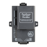
Figure 5. Power and RS485 pin outs
(Tx/+)
(Rx/-)
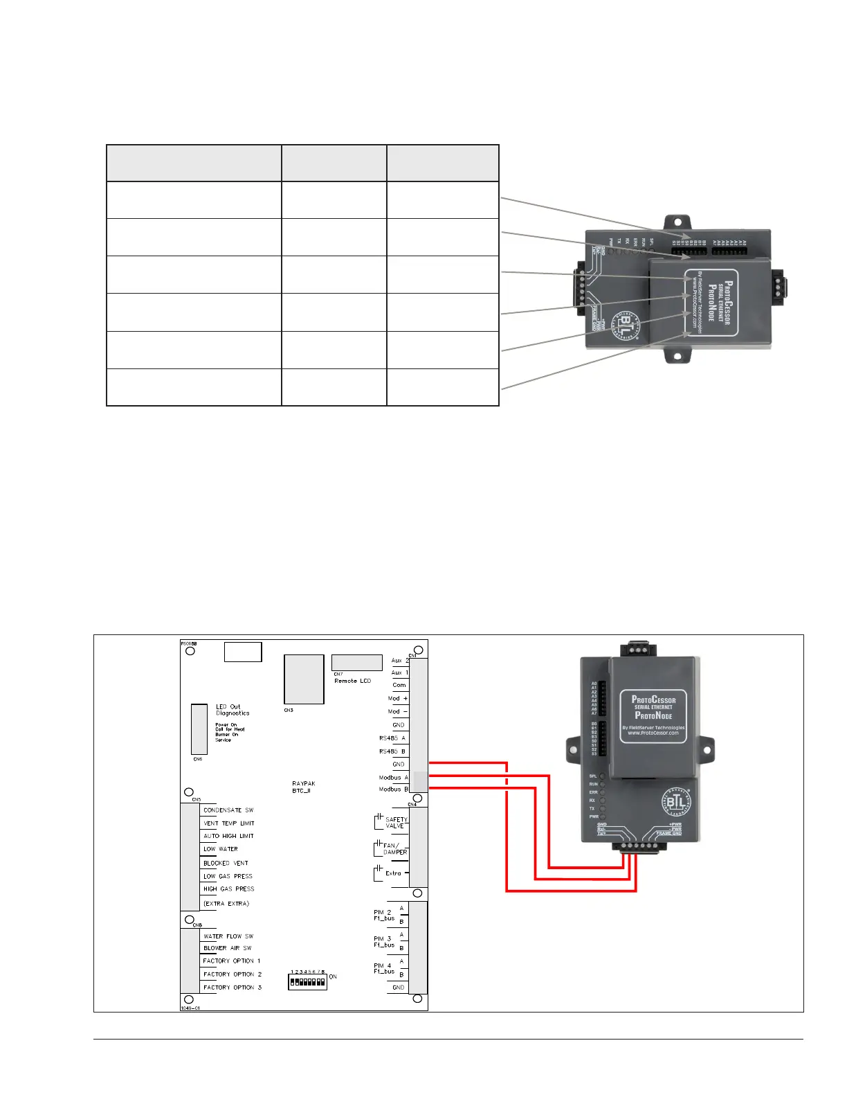
Connecting the VERSA IC Modbus port to the
ProtoNode’s Phoenix 6 pin connector.
• Connect VERSA IC Modbus pin A (RS485+) to the ProtoNode’s pin 1 (RS485+) on the Phoenix 6 pin connector.
• Connect VERSA IC Modbus pin B (RS485-) to the ProtoNode’s pin 2 (RS485-) on the Phoenix 6 pin connector.
• Connect VERSA IC Modbus pin GND (Ground) and the ProtoNode’s pin 3 (Signal Ground) on the Phoenix 6 pin
connector.
Figure 6. VERSA IC Modbus RS485 pin outs to the ProtoNode’s Modbus port
Raypak Pin # ProtoNode Pin Assignment
MODBUS A (+) Pin 1 RS-485 +
MODBUS B (-) Pin 2 RS-485 -
MODBUS GND Pin 3 RS-485 GND
Power In (+) Pin 4 V +
Power In (-) Pin 5 V -
Frame Ground Pin 6 Frame GND
APPROVED
UNCONTROLLED DOCUMENT IF PRINTED