22
EZ-LINK Electrical Requirements
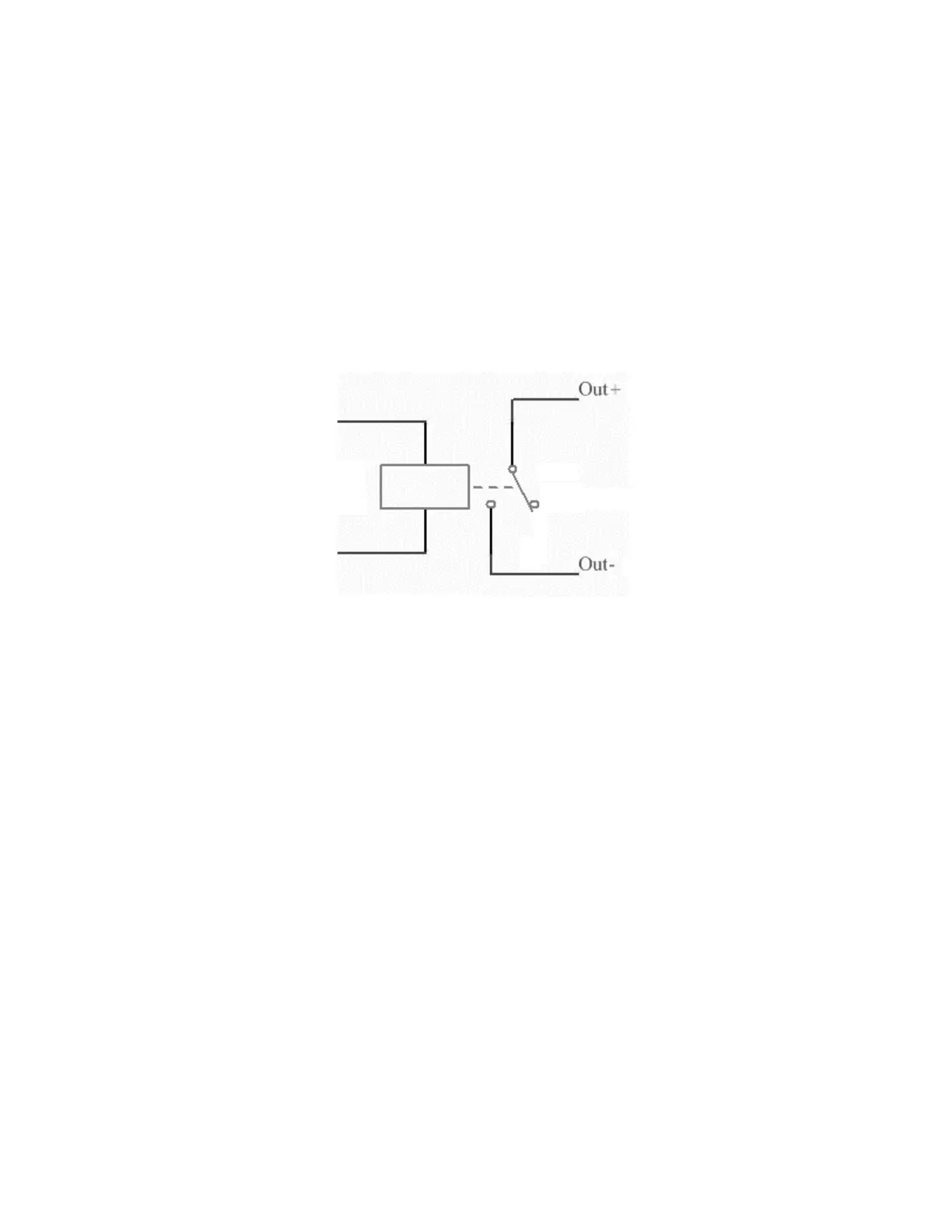
Figure 2 below shows the required circuit for the output on the laser’s filter control system. When the
laser’s filter control unit wishes to turn on the exhaust system, the contacts on the relay are closed, thus
connecting the two output pins. These output pins correspond to pins 4 & 5 on the exhaust system.
When creating a circuit to detect when these two wires have been connected, no more than 200 mA
may pass through these wires.
Figure 2: The circuit for the "start exhaust system" signal.
When creating the “Check Filter” signal, the two wires for the signal should be shorted together using a
relay. This means that the exhaust system will not actively dump any current through these wires. The
laser’s filter control unit should use approximately 30 mA to detect when those wires have been
connected.
EZ-LINK Control Operations
The filter control operation is very simple. When a user begins to run a laser engraving/cutting job, the
filter controller turns on the exhaust system immediately. When the job has been cancelled, paused, or
finished, the laser’s filter control unit should wait 15 seconds or more before turning off the exhaust
system. This allows any extra fumes to be evacuated from the laser engraver.